Proximity sensors
The most common form of pneumatic sensor is the interruptible jet, the principle of which is shown in Figure 1.Supply and receiver pipes are aligned axially, separated by a gap. The intrusion of any solid object into the gap, interrupting the jet, causes the pressure in the receiver to fall to atmospheric. This change in pressure is used to operate a switching element controlling an appropriate circuit, for example a counting circuit. The switching element is normally a transducer giving an electric signal output.
This type of sensor has the advantage that it is not critical on gap dimensions, can change its state rapidly for counting purposes and is not sensitive to shape or texture. Its main disadvantage is that atmospheric air is entrained in the receiver and if contaminated, can interfere with the performance.
The limitation can be overcome by lightly pressurising the receiver in the opposite direction (Figure 2). The main jet then impinges on the secondary jet, applying back pressure which increases the receiver pressure. An object interfering with the main jet cuts off this back pressure and the receiver pressure falls back to its normal level. Under both conditions there is always outflow from the receiver which cannot therefore entrain
Both of these types require small nozzle sizes in the supply to achieve laminar flow. The effective gap length is the distance over which the laminar flow can be maintained.
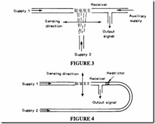
An alternative shown in Figure3 uses a third jet placed at right angles to the main supply jet. The receiver may or may not be pressurised. This works on the principle of a turbulence amplifier, with the main jet flow, normally laminar, being rendered turbulent by the impingement of the sidejet, reverting to laminar flow when the sidejet is interrupted. The practical measuring gap, which is between the sidejet and the main jet can be made much larger for the same pressure difference in the receiver.
A more practical form of interrupted sensor with back flow from the receiver is shown in Figure 4, back flow being obtained from the same supply but with pressure reduced by a restrictor. Sensors of this type can be expected to have a maximum gap of about 20 mm working off a supply pressure of about 0.1 bar.
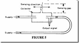
The system shown in Figure 5 is capable of working with larger gaps at the same pressure levels. Here a collector is incorporated to supply a second external gap (the sensing gap), with output signal derived from the same position as before. This device is known as an airstream detector.
Back pressure sensors are effective when the object to be sensed can pass close to the
jet. A single jet is used in this case, the presence of an object modulating the flow and causing a pressure change at the output (Figure 6). It can be used to measure objects moving towards or away from it as well as across it, with suitable signal amplification.
The conical jet sensor is a further type where thejet emerges from an annular nozzle and is of divergent conical form. Air inside the cone is entrained, resulting in a region of reduced pressure, sensed by the output; the depression and therefore the output signal strength, is modified by the asymmetric distortion of the conical jet resulting from its impingement on a downstream object. It is rather slower in response than other types of interruptible jet sensors and requires a higher air flow.
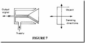
The reverse configuration or cone jet, Figure 7, employs an annular nozzle to produce a convergent conical jet. When this impinges on an object, pressure is increased within the cone, creating a back pressure through the outlet.
All single jet devices are free from contamination in conditions of dirty ambient air, however they do work with small orifice sizes, so the quality of the supply air has to be good at least with a filtration level of 5 micron.
Bleed sensors
Where contact with the sensed object is possible there are some other forms of pneumatic sensors as shown in Figure 8: a simple incorporated bleed sensor, a ball roller bleed sensor
and a “cat’ s whisker” sensor. These are capable of working on moderately high pressures if the sensed object is heavy enough to tolerate the resulting force. A ball roller requires a small movement to displace the ball and send a signal, and a eat’s whisker distorts a tightly wound spring which allows pressure to escape (Figure 9).
Fluidic proximity sensor
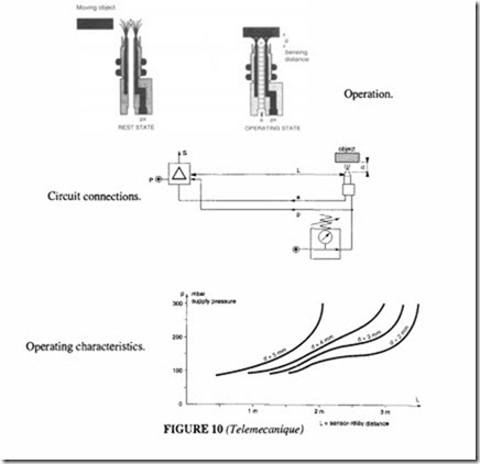
This type of sensor is shown in Figures IOand II. These work on low pressures up to about 200 mbar and distances up to 5 mm. The output signal is low (of the order of2 mbar), so an amplifier or pneumatic relay is required to produce a workable signal.
Pneumatic amplifier
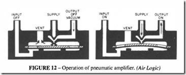
An amplifier of this type is required to switch a small pneumatic pressure signal, which may be as low as 2 mbar to a usable pressure of 8 bar, representing a switching ratio of 4000: 1.The usual construction of such a device incorporates a diaphragm as illustrated in Figure 12.
When the input signal is below the actuating level, a flat spring holds the pilot diaphragm away from the opening between the output chamber and the vented chamber. A jet of supply air passes through the output chamber and the vented chamber, drawing air with it from the output chamber and causing the output pressure to be slightly negative.
When the input signal is above the actuating level, the diaphragm seals the opening between the output chamber and the vented chamber. The total supply flow passes to the output port. A dead-ended load will receive the full supply pressure.
When setting up a sensing system, the designer has to take account of the advantages and disadvantages of pneumatic sensing versus an alternative electronic sensor. It may be more effective to use electronics at this stage, and an electronic/ pneumatic interface at the power stage.
Non-pneumatic proximity sensors
In any control system it makes sense to use the most appropriate device whatever the principle of operation, so it is worthwhile dealing with some of the alternative forms of sensor based on electronics since in some circumstances it may be preferable to use one of them as part of a primary pneumatic system.
There are three forms of non-contacting sensors – inductive, capacitive and photo electric.
Inductive sensors detect ferrous and non-ferrous metals without physical contact; the detection distance depends on the type of metal; non-ferrous metals have a distance reduced to about 0.3 times that for steel. Very high switching speeds are possible, up to 5000Hz. According to type the sensing range for mild steel is between Imm and 20 mm. Capacitive sensors are similar to inductive sensors but can also detect non-metallic materials with reduced sensitivity. They can also detect through other materials, so they can be mounted externally on non-metallic containers to sense filling levels. The sensing rate is slower, up to 400 Hz, with a maximum sensing distance of I0 mm.
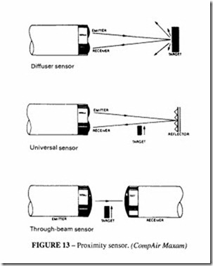
Photoelectric sensors use a pulsed red or infra-red beam produced by a solid state (LED) light source; there are three variants of this type- diffuse, universal and through-beam sensors, Figure 13. The sensing rate is up to 200 Hz.
The diffuse beam sensor gives good sensing reliability under adverse conditions ofhigh ambient light or dusty and smoky atmospheres; it has the emitter and receiver mounted in the same housing and relies on light scatter from the object being picked up by the receiver. The sensing distance is up to 150 mm.
The universal sensor is similar to the diffuse sensor but the optics are focused at a greater distance. The sensor is normally used with a prismatic reflector and signals when the light beam is broken. The sensing distance is up to 2.5 m.
In a through beam sensor, the emitter and receiver are separately mounted facing one another. When an object interrupts the beam a signal is given. A range of up to 10 metres is possible.
Fibre optic sensors
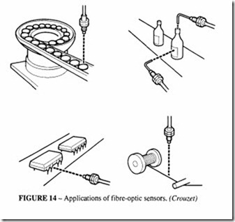
The photo-electric sensors may be too bulky or awkward for direct mounting. In this case fibre-optic types can be used, Figure 14; they are capable of sensing object sizes as small as 0.1 mm, so they can be used for sensing thin wires or threads. The light emitter and receiver are mounted remotely at a convenient situation.

