With change of distance
If a system operates satisfactorily in conveying a material over a given distance it is quite possible that the pipeline will block if the pipeline is extended and it is required to convey the material over a longer distance. A change of pipeline routing that requires an increase in the number of bends in the pipeline can also affect performance. Even a change of existing bends in a pipeline, to bends having a different geometry for example, can influence performance, as considered in Section 14.5.2.
Material feed rate
For a given value of conveying line pressure drop, the conveying capacity of a pipeline will decrease with increase in distance. For a change in conveying distance, therefore, there must be a corresponding change of material feed rate into the pipeline.
This point is illustrated in Figure 20.13. This is a plot of material flow rate drawn against conveying distance, with the influence of conveying line pressure drop shown. It represents the approximate capability of an 81 mm bore pipeline with a material only capable of being conveyed in dilute phase in a conventional conveying system. It shows that for a given conveying line pressure drop the material flow rate is approximately inversely proportional to conveying distance. This is for illustrative purposes only, since it is the ‘equivalent length’ of a pipeline that is the important parameter and this includes allowances for vertical lift and number and geometry of bends.
From Figure 20.13 it will be seen that the lines slope steeply for short conveying distances. For a given conveying line pressure drop, therefore, material flow rate cap- ability will change significantly for just small increases in conveying distance with short pipelines. This is a direct consequence of the scaling model for conveying length, as considered in Section 14.3.2.2. To maintain the same material flow rate over a longer distance will require a significant increase in pressure drop. If a higher pres- sure is not available the pipeline will block if the material flow rate is not reduced to compensate.
Air flow rate
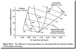
If the conveying distance is increased, the material flow rate will have to decrease. This will result in the material being conveyed at a lower value of solids loading ratio. For a material capable of being conveyed in dense phase, in a conventional system, this will mean that a slightly higher value of conveying line inlet air velocity will have to be employed. This, in turn, means that a higher flow rate of air will have to be used to convey the material. The potential influence of solids loading ratio on conveying line inlet air velocity for dense phase flow was illustrated earlier in Figure 18.4.
This point is illustrated with Figure 20.14. This is a plot of material flow rate against air flow rate for an 81 mm bore pipeline. It is presented for illustrative pur- poses only once again, since an 81 mm bore pipeline would not be appropriate for the very long distances considered. The change in the limit to conveying with increase in conveying distance is due to the gradual change from dense to dilute phase convey- ing that results from the gradual decrease in pressure gradient available for material conveying.
Conveying potential
In terms of conveying potential it is conveying line pressure gradient and material properties that are the important parameters. To convey in dense phase requires a high pressure gradient, because of the high concentration of the material in the air. Due to the compressibility problems with air, and expansion effects in particular, air supply pressures greater than about 5 bar gauge are rarely employed. If it is required to convey over a long distance, therefore, the pressure gradient must be reduced if it is not pos- sible to utilise a higher air supply pressure to compensate. If the pressure gradient has to be reduced it will not be possible to convey in dense phase.
Thus even if a material is capable of being conveyed in dense phase and at low velocity, the material will have to be conveyed in dilute phase, and at a much higher velocity, if it is required to convey the material over a long distance. A larger bore pipeline will have to be used, as an alternative to a higher air supply pressure, in order to achieve the material flow rate required.
If the properties of the material are such that it can only be conveyed in dilute phase, suspension flow, the use of high pressure air for conveying will have no effect at all in changing this to dense phase, unless a totally different conveying system is employed. The transition that occurs with dense phase materials that is depicted on Figure 20.14 is only appropriate for dense phase conveying. For materials that are only capable of dilute phase conveying the conveying limit will not vary with respect to conveying distance.
