Programmable controllers
Increasingly pneumatic and hydraulic sequences are controlled by programmable controllers (PCs, not to be confused with personal computers). They are often called PLCs for programmable logic controllers, although strictly speak- ing this is a registered trademark of Allen Bradley.
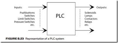
A PC consists of a computer adapted for process control and programmed in a manner which is easy for first-line technicians to understand. Signals from the plant (e.g. limit switches, photocell, pushbuttons, switches, etc.) are connected to a range of input cards and outputs to the plant (e.g. solenoids, contactors, lamps, etc.) are driven by output cards.
These signals are identified by an address which is based on their connection points into the PLC. For example, on an SLC500 the form is:
Other manufacturers’ schemes are similar, for example Siemens use I & Q (E & A in Europe for Eingang and Ausgang).
PCs also have a vast range of built-in functions: storage bits, timers, counters, sequencers, integer and floating point numbers, and much much more. With these it is quite straightforward to construct a hydraulic or pneumatic system
where all the solenoids and limit switches are solely connected back to a PC as shown in Figure 8.23.
This brings many advantages. The first is cost; PCs are very cheap. A simple PLC with eight inputs and four outputs costs, at the time of writing in early 2010, less than 100 Euros. It also simplifies the hydraulic or pneumatic piping, reducing installation costs in most applications. Second, it is easy to modify the system and make changes without re-piping. Finally, fault finding becomes much simpler be- cause each input can be clearly seen and each solenoid can be tested on its own.
PCs are commonly programmed using something called ‘Ladder Logic’. This mimics a relay circuit diagram using the American symbols of -] [- for a normally open contact (made when a signal is present) and -]/[- for a normally closed contact (made when a signal is absent).
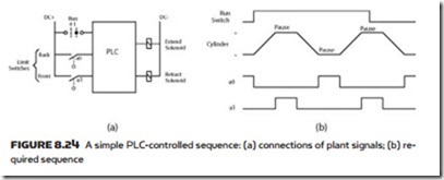
Figure 8.24a shows a very simple PLC system with three inputs and two outputs. The two solenoids control a single cylinder and the system is required to follow the sequence of Figure 8.24b, i.e. extend, pause, retract, pause and repeat until run is de-selected. When run is de-selected the cylinder retracts to the back limit switch.
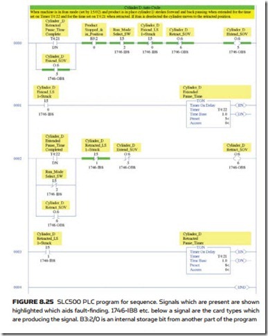
The program to achieve this is shown, written for an SLC500 PLC in Figure 8.25. The program is called a Ladder Diagram because it looks like the rungs of a ladder, and each statement is called a ‘Rung’.
Rungs 0 and 2 control the two solenoids. Rungs 1 and 3 provide the time de- lays for the pauses at the end of stroke. Note that in Rungs 0 and 2 the solenoids hold themselves on via a branch around the initiating timer signal.
Ladder Logic is not the only programming method. The IEC 1131 standard defines five programming methods:
• Ladder Rung (LD)
• Function Blocks (FBD) (AND gates, OR gates, SR memories, maths blocks, etc.)
• Statement List (STL) (simple text, e.g. LD X1 OR X2 ST Y0)
• Structured Text (ST) (structured high level language, similar to Pascal)
• Sequential Function Chart (SFC) (sequence diagram similar to Figure 8.26b). Whichever method is used the programming system will allow the state of the inputs and outputs to be observed from the programming device and changes can be made quickly and simply (e.g. adding manual controls to the example above).
distributed systems
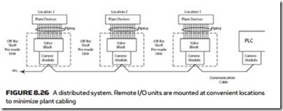
Early PLCs existed as a single control panel to which all signals had to cabled. Modern PLCs allow the input/output cards (called I/O) to be mounted remotely from the PLC processor, communication to/from all the I/O in one location taking place serially down single small cables. A hydraulic or pneumatic system will have the I/O cards pre-mounted at the manufacturers and will be delivered pre-wired and pre-tested to the project. A distributed system will look similar to Figure 8.26.
There are many advantages to this approach. It is, of course, much cheaper to install as the cabling is greatly reduced. Units such as skids, motor control centers and control desks can be tested prior to delivery, shortening the commissioning time. The system can also be easily expanded at a later date.
There are many standards for distributed systems. Amongst the most common are DeviceNet, Profibus DP, ASi-bus, Modbus and Control Net, all of which allow the I/O to be mounted remotely from the processor. Many manufacturers of pneumatic and hydraulic equipment now offer valve manifolds complete with built-in distributed system interfaces which greatly simplifies both piping and cabling.


