more complex sequences
The earlier sequence of Figures 8.6 and 8.7 translated easily into a practical circuit. In many cases, though, designing a circuit is less straightforward.
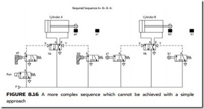
Suppose we have two cylinders, A and B, and four positional limits, but now the sequence required is A+, B+, B–, A–. Figure 8.16 shows the start of the design with shuttle valve Va controlling cylinder A and shuttle valve Vb control- ling cylinder B. Signal Xa extends the cylinder and will be controlled by limit a0 (saying the cylinder has retracted). Similarly signal Ya retracts the cylinder and will be controlled by limit b0 (saying cylinder B has retracted). However the limits a0 and b0 are piped and arranged examination will show that there is a point in the proposed cycle where one or both shuttle valves will have pressure applied to both sides of the valve at the same time. This problem is often known as a ‘locked-in’, maintained or trapped signal. There are several different ways in which this problem can be overcome.
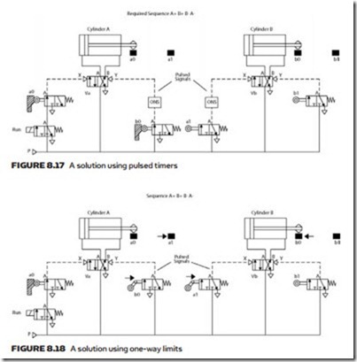
The first solution is to add one-shot pulse timers to the signals from limits b0 and a1. These pulses only last sufficiently long to shift the valve spool and pre- vent valves Va and Vb receiving pressure on both sides. This solution is shown in Figure 8.17.
The second solution uses the one-way limit shown earlier in Figure 8.8. Here, one-way limits are used for b0 and a1 which are active in the direction shown. These limits are arranged so the striker travels through the limit and produces a pulse in one direction but has no effect in the other direction. Effectively one-way limits are producing a single pulse when struck and the result is identical to that achieved with one-shot pulse timers in Figure 8.17. The one-way limit solution is shown in Figure 8.18.
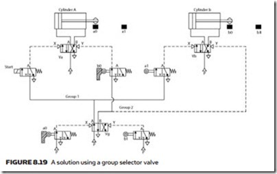
The third solution notes that the problem arises because cylinder B has to both extend and retract within the cycle of cylinder A. This observation
applies to any pneumatic sequence, if an actuator has to complete two movements within a single movement of another actuator a lock-in will probably result. To overcome this problem the cycle is split into two groups, as shown in Figure 8.19:
The sequence can be described in words as follows:
1. Initially both cylinders are retracted and a0 has moved valve Vg to apply pressure to group 1.
2. The start solenoid is energized and Va extends cylinder A. Limit a0 is un- struck then limit a1 is struck.
3. Limit a1 operates Vb and extends cylinder B.
4. Limit b1 is struck which shifts Vg to apply pressure to group 2.
5. Valve Vb now shifts and retracts cylinder B. Note there is no opposing signal via limit a1 because group 1 is depressurized.
6. Cylinder B retracts and limit b0 is struck. This operates Va, retracting cylinder A causing limit a0 to be struck when cylinder A is retracted.
7. Limit a0 shifts Vg depressurizing group 2 and repressurizing group 1 ready for the next cycle. We are now back at step 1.
The method of breaking a sequence down into smaller groups is a common way of handling very complex sequences.


