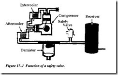
SAFETY VALVES
All compressed air systems that use a positive displacement compressor must be fitted with a pressure relief or safety valve that will limit the discharge or interstage pressures to a safe maximum limit. Most dynamic compressors must have similar protection because of restrictions placed on casing pressure, power input, and/or keeping out of surge range.
Two types of pressure relief devices are available, safety valves and relief valves. Although these terms are often used interchangeably, there is a difference between the two. Safety valves are used with gases. The disc overhangs the seat to offer additional thrust area after the initial opening. This fully opens the valve immediately, giving maximum relief capacity. These are often called pop-off safety valves.
With relief valves, the disc area exposed to overpressure is the same whether the valve is open or closed. There is a gradual opening, the amount depending upon the degree of overpressure. Relief valves are used with liquids where a relatively small opening will provide pressure relief.
Positive-displacement machines use safety valves. There are ASME standards of materials and sizing, and only ASME-stamped valves should be used. The relieving capacity of a given size of safety valve varies materially with the make and design. Care must be taken to ensure proper selection.
An approved safety valve is usually of the “huddling chamber” design. In this valve the static pressure acting on the disc area causes initial opening. As the valve pops, the air space within the huddling chamber between seat and the blowdown ring fills with pressurized air and builds up more pressure on the roof of the disc holder. This temporary pressure increases the upward thrust against the spring, causing the disc and its holder to lift to full pop opening.
After a predetermined pressure drop, which is referred to as blowdown, the valve closes with a positive action by trapping pressurized air on top of the disc holder. The pressure drop is adjusted by raising or lowering the blowdown ring. Raising the ring increases the pressure drop; lowering it decreases the drop.
Most state laws and safe practice require a safety relief valve ahead of the first stop valve in every positive-displacement compressed air system. It is set to release at 1.25 times the normal discharge pressure of the compressor or at the maximum working pressure of the system, whichever is lower. The relief valve piping system sometimes includes a manual vent valve and/or a bypass valve to the suction to facilitate startup and shutdown operations. Quick line sizing equations are
(1) line connection, d/1.75;(2) bypass, d/4.5; (3) vent, d/6.3; and (4) relief valve port, d/9.
The safety valve is normally situated atop the air reservoir. There must be no restriction on all blow-off points. Compressors can be hazardous to work around because they do have moving parts. Ensure that clothing is kept away from belt drives, couplings, and exposed shafts.
In addition, high-temperature surfaces around cylinders and discharge piping are exposed. Compressors are notoriously noisy. For this reason, ear protection should be worn. When working around highly pressurized air systems, wear safety glasses and do not search for leaks with bare hands. High-pressure leaks can cause severe friction bums.
