Rotary Screw Compressors
The most common reason for compressor failure or component damage is process instability. Rotary screw compressors are designed to deliver a constant volume and pressure of air or gas. These units are extremely susceptible to any change in either inlet or discharge conditions. A slight variation in pressure, temperature, or volume can result in instantaneous failure. The following are used as indices of instability and potential problems: rotor mesh, axial movement, thrust bearings, and gear mesh.
Rotor mesh. In normal operation, the vibration energy generated by male and female rotor meshing is very low. As the process becomes unstable, the energy due to the rotor-meshing frequency increases, with both the amplitude of the meshing frequency and the width of the peak increasing. In addition, the noise floor surrounding the meshing frequency becomes more pronounced. This white noise is similar to that observed in a cavitating pump or unstable fan.
Axial movement. The normal tendency of the rotors and helical timing gears is to gen erate axial shaft movement, or thrusting. However, the extremely tight clearances between the male and female rotors do not tolerate any excessive axial movement, and therefore, axial movement should be a primary monitoring parameter. Axial mea surements are needed from both rotor assemblies. If there is any increase in the vibra tion amplitude of these measurements, it is highly probable that the compressor will fail.
Thrust bearings. Although process instability can affect both the fixed and float bear ings, the thrust bearing is more likely to show early degradation as a result of process instability or abnormal compressor dynamics. Therefore, these bearings should be monitored closely and any degradation or hint of excessive axial clearance should be corrected immediately.
Gear mesh. The gear mesh vibration profile also provides an indication of prolonged compressor instability. Deflection of the rotor shafts changes the wear pattern on the helical gear sets. This change in pattern increases the backlash in the gear mesh, results in higher vibration levels, and increases thrusting.
Reciprocating Positive-Displacement Compressors
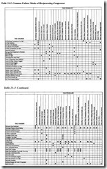
Reciprocating compressors have a history of chronic failures that include valves, lubrication system, pulsation, and imbalance. Table 21-3 identifies common failure modes and causes for this type of compressor.
Like all reciprocating machines, reciprocating compressors normally generate higher levels of vibration than centrifugal machines. In part, the increased level of vibration is due to the impact as each piston reaches top dead center and bottom dead center of its stroke. The energy levels also are influenced by the unbalanced forces generated by non-opposed pistons and looseness in the piston rods, wrist pins, and journals of the
compressor. In most cases, the dominant vibration frequency is the second harmonic (2x) of the main crankshaft’s rotating speed. Again, this results from the impact that occurs when each piston changes directions (i.e., two impacts occur during one com plete crankshaft rotation).
Valves. Valve failure is the dominant failure mode for reciprocating compressors . Because of their high cyclic rate, which exceeds 80 million cycles per year, inlet and discharge valves tend to work-harden and crack.
Lubrication systems. Poor maintenance of lubrication-system components, such as fil ters and strainers, typically causes premature failure. Such maintenance is crucial to reciprocating compressors because they rely on the lubrication system to provide a uniform oil film between closely fitting parts (e.g., piston rings and the cylinder wall). Partial or complete failure of the lube system results in catastrophic failure of the compressor.
Pulsation . Reciprocating compressors generate pulses of compressed air or gas that are discharged into the piping that transports the air or gas to its point(s) of use. This pulsation often generates resonance in the piping system, and pulse impact (i.e., standing waves) can severely damage other machinery connected to the compressed air system. Although this behavior does not cause the compressor to fail, it must be prevented to protect other plant equipment. Note, however, that most compressed-air systems do not use pulsation dampers.
Each time the compressor discharges compressed air, the air tends to act like a com pression spring. Because it rapidly expands to fill the discharge piping’s available vol ume, the pulse of high-pressure air can cause serious damage. The pulsation wavelength, A., from a compressor having a double-acting piston design can be deter mined by
For a double-acting piston design, a compressor running at 1,200 rpm will generate a standing wave of 28.4 feet. In other words, a shock load equivalent to the discharge pressure will be transmitted to any piping or machine connected to the discharge pip ing and located within twenty-eight feet of the compressor. Note that, for a single acting cylinder, the wavelength will be twice as long.
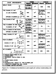
Imbalance. Compressor inertial forces may have two effects on the operating dynam ics of a reciprocating compressor, affecting its balance characteristics. The first is a force in the direction of the piston movement, which is displayed as impacts in a vibration profile as the piston reaches top and bottom dead center of its stroke. The second effect is a couple, or moment, caused by an offset between the axes of two or more pistons on a common crankshaft. The interrelationship and magnitude of these two effects depend upon such factors as (1) number of cranks; (2) longitudinal and angular arrangement; (3) cylinder arrangement; and (4) amount of counterbalancing possible. Two significant vibration periods result, the primary at the compressor’s rotation speed (x) and the secondary at 2x.
Although the forces developed are sinusoidal, only the maximum (i.e., the amplitude) is considered in the analysis. Figure 21-1 shows relative values of the inertial forces for various compressor arrangements.


