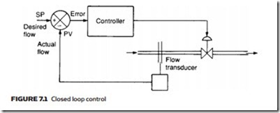
If some industrial process is to be automatically controlled, there will be many process variables (e.g. temperature, flow, pressure, level) which need to be measured and kept at the correct value for safety and economical operation. In Figure 7.1, for example, water flow in a pipe is to be kept at some preset value.
In Figure 7.1 the flow is measured to give the current value (usually termed PV for process variable). This is compared with the required flow (called SP for set point) to give an error signal, which is passed to a controller. This adjusts the actuator drive signal to move the valve in the direction to give the required flow (i.e. PV = SP, giving zero error). The arrangement of Figure 7.1 is called closed loop control because a loop is formed by the controller, actuator and measuring device.
In many plants, closed loop control is achieved by electronics, or even computer, techniques with the various signals represented by electric currents. A common standard uses a current within the range 4–20 mA. If this represents a water flow from 0 to 1500 L min−1, for example, a flow of 1000 L min−1 is represented by a current of 14.67 mA.
Electrical representation, and electronic devices, are not the only possibility, however. Process control history goes back before the advent of electronics (some early examples being speed governors on steam engines and an early servosystem for ships’ rudders designed by Isambard Kingdom Brunel). Much of the original process control work was based around pneumatic devices, with the various signals represented by pneumatic pressures.
Perhaps surprisingly, pneumatic process control has by no means been super- seded by electronic and microprocessor technology, so it is worth looking at the reasons for its popularity. First and foremost is safety. Much process control is done in chemical or petrochemical plants where explosive atmospheres are common. If electrical signals are used, great care must be taken to ensure no possible fault can cause a spark, which could ignite an explosive atmosphere. While this can be achieved, the result is complex and maintenance may be difficult (test instruments must also be classified safe for use in an explosive atmosphere).
A pneumatic system contains only air, so it presents no hazard under these conditions. No particular care needs to be taken with installation, and maintenance work can be carried out ‘live’ with simple non-electrical test
A great deal of design and application experience has evolved over the years, and this base of knowledge is another major reason for the continuing popular- ity of pneumatic control. Companies with a significant investment in pneumatic control and a high level of staff competency are unlikely to change.
Many devices in the loop are, in any case, best provided by pneumatic techniques. Although electrical actuators are available, most valves are driven by pneumatic signals – even when transducer and controller are electronic.
signals and standards
Signals in process control are generally represented by a pressure which varies over the range 0.2–1.0 bar or the almost identical imperial equivalent 3–15 psig. If the water flow of 0–1500 L min−1 is represented pneumatically, 0 L min−1 is shown by a pressure of 0.2 bar, 1500 L min−1 is 1.0 bar, while 1000 L min−1 is 0.733 bar.
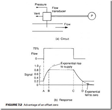
The lower-range pressure of 0.2 bar (3 psig in the imperial range) is known as an offset zero and serves two purposes. First is to warn about damage to signal lines linking the transmitter and the controller or indicator (the 4 mA offset zero of electrical systems also gives this protection). In Figure 7.2a a pneumatic flow transmitter is connected to a flow indicator. A pneumatic supply (typically, 2–4 bar) is connected to the transmitter to allow the line pressure to be raised. The transmitter can also vent the line to reduce pressure (corresponding to reducing flow). If the line is damaged it is probably open to atmosphere giving a pressure of 0 bar, regardless of the transmitter’s actions. As the indicator is scaled for 0.2–1 bar, a line fault therefore causes the indicator to go offscale, negatively. Loss of the pressure supply line causes a similar fault indication.
The offset zero also increases the speed of response. In Figure 7.2b a sudden increase in flow is applied to the transmitter at time A. The flow transmitter connects the supply to the line, causing an exponential increase in pressure (with a time constant determined by the line volume). The pressure rises towards the supply pressure, but at time B the correct pressure of 0.8 bar is reached, and the transmitter disconnects the supply.
The pressure stays at 0.8 bar until time C, when the flow rapidly falls to zero. The transmitter vents the line and the pressure falls exponentially to- wards 0 bar (with time constant again determined by line volume). At time D, a
pressure of 0.2 bar is reached (corresponding to zero flow) and the transmitter stops venting the line. For increasing indication, the offset zero has little effect, but for decreasing indication, the transmitter would need to completely vent the line without an offset zero to give zero indication. With a first-order lag response, this will theoretically take an infinite time, but even with some practical acceptance of error, time CD will be significantly extended.
Speed of response is, in any case, the Achilles heel of pneumatic signals. With an infinitely small time constant (given by zero volume lines), the best possible response can only be the speed of sound (330 m s−1). If signal lines are over a hundred meters or so in length, this transit delay is significant. To this is added the first-order lag caused by the finite volume of the line, and the finite rate at which air flows into or out of the line under transmitter control. For a fast response, line volume must be small (difficult to achieve with long lines) and the transmitter able to deliver or vent large flow rates. In practice, time constants of several seconds are quite common.

