MEASURING SUCCESS
In any program we must track success in order to have support from management and maintenance personnel. We must also understand that any action will have a reaction, which will possibly be negative. We know that successful maintenance programs will provide success but we must have a system of checks and balances to ensure that we’re on track.
In order to measure success of a hydraulic maintenance program, we must have some way of tracking success. First, we need to establish a benchmark. A benchmark is a method by which we will establish certain key measurement tools that will tell you the current status of your hydraulic system, and then tell you if you’re succeeding in your maintenance program.
Before you begin the implementation of your new hydraulic maintenance program, it would be helpful to identify and track the following information.
Track All Downtime
As in any other type of critical plant system, all delays that affect a hydraulic system’s performance should be accurately tracked. The data compiled can then be used to identify inherent design, installation, operation, or maintenance problems that may contribute to its poor reliability. The tracking program should include the following data:
• What component failed?
• Cause of failure?
• Was the problem resolved?
• Could this failure have been prevented?
In addition to tracking the failure mode of hydraulic systems or their components, the program should include an accurate compilation of costs that are incurred as a result of reduced reliability, failures, or poor performance. These costs should include parts and material; labor cost required to repair; lost production; and any other incremental costs that were directly or indirectly caused by the hydraulic system.
Hydraulic Fluid Analysis
Hydraulic fluid becomes contaminated over time or when poor operating and maintenance practices are used. Therefore, an effective preventive maintenance program must include periodic testing of these fluids. In general service applications, representative hydraulic fluid samples should be collected and analyzed on a 30-day interval. Each sample should be tested for the following:
• Copper content
• Silicon content
• Free water
• Iron content
• ISO particulate count
• Fluid condition, i.e., viscosity, additives, and oxidation
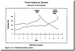
When the tracking process begins, you need to trend the information that can be trended (Figure 11-3). These trends let you identify degradation in hydraulic fluid quality that can lead to premature wear, poor performance, or catastrophic failure of critical hydraulic components or systems.
RECOMMENDED MAINTENANCE MODIFICATIONS
Modifications to an existing hydraulic system need to be accomplished professionally. Modifying a hydraulic system in order to improve maintenance efficiency is impor tant to a company’s goal of maximum equipment reliability and reduced maintenance cost.
1. Filtration Pump with Accessories
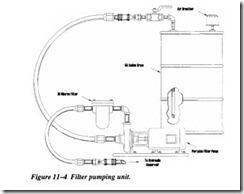
Objective. The objective of this pump and modification is to reduce contamination that is introduced into an existing hydraulic system by the addition of new fluid and the device used to add oil to the system (Figure 11-4).
Additional information. Hydraulic fluid from the distributor is usually not filtered to the requirements of an operating hydraulic system. Typically, this oil is strained to a mesh rating and not a micron rating. How clean is clean? Generally, hydraulic fluid must be filtered to 10 microns absolute or less for most hydraulic systems; 25 microns is the size of a white blood cell, and 40 microns is the lower limit of visibility with the unaided eye.
Many maintenance organizations add hydraulic fluid to a system through a contaminated funnel. They may even use a bucket that has contained other types of fluids and lubricants, without cleaning it first.
Recommended equipment and parts.
• Portable filter pump with a filter rating of 3 microns absolute
• Quick disconnects that meet or exceed the flow rating of the portable filter pump.
• A 3/4-inch pipe long enough to reach the bottom of the hydraulic container your fluids are delivered in from the distributor.
• A 2-inch reducer bushing to 3/4-inch npt to fit into the 55-gallon drum, if you receive your fluid by the drum. Otherwise, mount the filter buggy to the double-wall “tote” tank supports, if you receive larger quantities.
• Reservoir vent screens should be replaced with 3/1O-micron filters, and openings around piping entering the reservoir should be sealed.
Show a double-wall tote tank of about 300 gallons mounted on a frame for fork truck handling, with the pump mounted on the framework.
Also show pumping from a drum mounted on a frame for fork truck handling, sitting in a catch pan, for secondary containment, with the filter buggy attached.
Regulations require that you have secondary containment, so make everything “leak” into the pan.
2. Modify the Hydraulic Reservoir
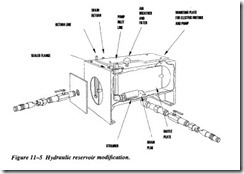
Objective. The objective is to eliminate the introduction of contamination through oil being added to the system or contaminates being added through the air intake of the reservoir. A valve needs to be installed for oil sampling (Figure 11-5).
Additional information. The air breather strainer should be replaced with a 10-micron filter if the hydraulic reservoir cycles. A quick disconnect should be installed on the bottom of the hydraulic unit and at the three-quarter level point on the reservoir with valves to isolate the quick disconnects in case of failure. This allows the oil to be added from a filter pump as previously discussed and would allow for external filter ing of the hydraulic reservoir oil if needed. Install a petcock valve on the front of the reservoir that will be used for consistent oil sampling.
Equipment and parts needed.
• Quick disconnects that meet or exceed the flow rating of the portable filter pump
• Two gate valves with pipe nipples
• One 10-micron filter breather
WARNING: Do not weld on a hydraulic a reservoir to install the quick disconnects or air filter.


