Gear pump
Gear pumps as the name suggests make use of the principle of two gears in mesh in order to generate pumping action. They are compact, relatively inexpensive and have few moving parts. Gear pumps are further classified as:
• External gear pumps
• Internal gear pumps
• Lobe pumps and
• Gerotor pumps.
External gear pump
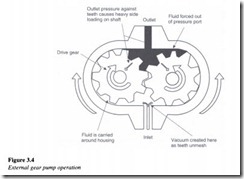
A schematic of an external gear pump is shown in Figure 3.4.
An external gear pump consists of two gears usually equal in size, which mesh externally and are housed in a pump case. Each gear is mounted on a shaft, which is supported by needle bearings in the case covers. One of these shafts is coupled to a prime mover and is called the drive shaft. The gear mounted on this shaft is called the drive gear. It drives the second gear as it rotates. Two side plates are provided one on each side of the gear. The side plates are held between the gear case and case covers.
The suction side is where the teeth come out of the mesh. The volume expands in this region leading to a drop in pressure below the atmospheric value, which results in the fluid getting pushed into this void. The fluid is trapped between the housing and the rotating teeth of the gears. The discharge side is where the teeth go into the mesh and here the volume decreases. Since the pump has a positive internal seal against leakage, the fluid is forced into the outlet port. The mating gears prevent the delivery side oil from flowing to the suction side. This is how flow is created by the pump, thereby transferring energy under pressure from the input source to a fluid power actuator.
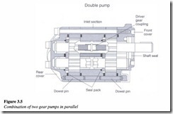
The amount of displacement in gear pumps is determined by the number of gear teeth, the volume of fluid between each pair of teeth and the speed of rotation. One important point to be noted here is that a fixed volume of fluid is delivered by the pump for each rotation. The limiting factors as far as the pump performance is concerned are the amount of leakage and the pump’s ability to withstand the pressure differential between the inlet and the outlet ports. These pumps can be designed either as single-chamber devices or multi-chamber devices as shown in Figure 3.5.
The multiple chamber devices are largely designed in order to increase the pump flow capacity, and consists of either individual units connected in parallel or by providing many pumps on a single shaft by isolating the inlets and the outlets. One important drawback with external gear pumps is the unbalanced side load on its bearings, caused due to high pressure at the outlet and low pressure at the inlet which in tum results in slower speeds and lower pressure ratings in addition to reducing the bearing life.
It is important for a gear pump to have the following:
• Close meshing of gears
• A very small clearance between the gear teeth and housing and also between the side plates and gear face.
Two mating teeth coming into mesh during normal operation of a gear pump will trap oil in the root section. Should there be no way for this oil to escape, an extremely high pressure would momentarily occur, thereby making the pump run with a great pounding or rattling noise. As the gear rotates, the ‘trapping space’ transmits from the discharge side to the suction side. The space gets smaller towards the center, becomes a minimum at the center and thereafter begins to increase.
In order to prevent the pounding or rattling of the pump, a relief recess is provided in the side plate, at a location corresponding to the trapping space in the meshing area. The recess extends only over that part of the trapping space. The pressurized oil is bled back to the discharge side through the recess. By the time the two teeth have arrived at their parting position, the trapping space will be way off the recess and so no internal communication occurs between the discharge and suction side through this recess.
During the course of overhauling/reconditioning of these pumps, a general tendency to carry out additional machining on the side plate in order to elongate the existing recess in excess of the specified length has been observed. This should be avoided, because too long a recess allows internal communication between the suction and discharge sides through it, even after the two teeth are parted from each other.
It is also equally important to ensure the correct positioning of the side plates at the time of pump build up, during overhaul. Should a side plate be placed in the reverse position, the recess comes into the position over the discharge side of the pump, thereby keeping the oil blocked in the trapping area.
The side plates in gear pumps are generally replaceable. The replacement is usually carried out during overhaul, if the clearance between the gear case and side plates has exceeded the allowable clearance limit specified by the manufacturer.
The following analysis evaluates the theoretical flow rate of a gear pump: Let
Do be the outside diameter of the gear teeth
Di be the inside diameter of gear teeth
L be the width of gear teeth
vd be the displacement volume of the pump
N be the speed of the pump and
Qr be the theoretical pump flow rate.
From gear geometry, the volumetric displacement can be calculated from the equation:
The theoretical flow rate is given by:
However, as seen from the graph, the actual flow rate Qa of the pump will be lower than the theoretical flow rate Qt, as a result of internal leakage in the pump.
Internal leakage of oil
Oil from the high-pressure side usually tends to leak into the low-pressure side through any existing clearance. In a gear pump there is a running clearance between the gears and the case, which provides a path for leakage of oil. This results in a small amount of oil being continuously transferred to the low-pressure suction side from the high-pressure discharge side, in the form of internal leakage. This internal leakage of oil is known as pump slippage. This oil tends to flow along the shaft and then through the grooves provided on the back face of the side plate. From these grooves the oil enters the suction side through a drilled oil way provided in the pump case. It is this internal leakage oil that lubricates the needle bearings in the pump.
As a result of this leakage it is quite obvious that the actual flow rate of the gear pump will be less than the theoretical flow rate. The ratio of the actual flow rate and the theoretical flow rate is called the ‘volumetric efficiency’ of the pump which is represented by the symboll]v
The higher the pump discharge pressure (resulting from a heavy load or resistance to flow in the hydraulic system) greater will be the internal leakage along with a correspondingly lower volumetric efficiency.
An abnormally high increase in pump discharge pressure apart from causing excessive internal leakage also results in a heavy load on the pump bearings. Consequently, the bearing life gets reduced while also causing all the gear teeth to scuff the bore wall, thereby resulting in damage to the pump.
As such, a gear pump or for that matter any positive displacement pump, requires protection from high pressures as discussed earlier. This is usually accomplished by incorporating a safety device called a ‘relief valve’. Standard gear pumps are used at operating pressures and capacities up to 80 kg/cm2 (1138 psi) and 700 liter/min (185 gpm) respectively, with peak pressure conditions varying between 120 (1707 psi) and 150 kg/cm2 (2133 psi).
Gear pumps, which use spur gears (teeth parallel to the gear axis), are noisy in operation especially at high speeds. The use of helical gears (teeth inclined at a small angle to the gear axis) reduces the noise level and provides for smoother operation. However helical gears are expensive and are also limited to low-pressure applications. Another disadvantage with helical gears is the excessive end thrust that develops during the course of its operation. Herringbone gears are a good alternative especially in applications requiring higher pressures. They basically consist of two rows of helical teeth cut into one gear. One row in each gear is right-handed, while the other is left handed. This is done to cancel out the axial thrust. A major plus point with these gears is the elimination of the end thrust. Additionally, they also provide smooth operation with a higher flow rate.
The pump case is a casting, with its bores machined in such a way as to provide a greater radial clearance on the suction side than on the discharge side in the quiescent state. This inequality is calculated to equalize the clearance when the pump is in its normal operating condition. In smaller-sized pumps the radial clearance on the discharge side is about 0.03 mm while in larger-sized pumps it is about 0.05 mm. The clearance on the suction side is about three times larger.
Internal gear pump
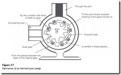
Internal gear pump is another variation of the basic gear pump. Figure 3.7 illustrates clearly, the internal construction and operation of an internal gear pump. The design consists of an internal gear, a regular spur gear, a crescent-shaped seal and an external housing. As power is applied to either gear, the motion of the gears draws the fluid from the suction, and forces it around both the sides of the crescent seal. This acts as a seal between the suction and discharge ports. When the teeth mesh on the side opposite to the crescent seal, the fluid is forced out through the discharge port of the pump. Similar to the external gear pump, internal gear pumps also have an in-built safety relief valve.
Lobe pump
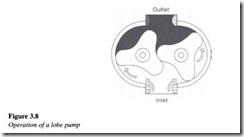
The lobe pump is yet another variation of the basic gear pump. This pump operates in a fashion quite similar to that of an external gear pump, but unlike external gear pumps, the gears in these pumps are replaced with lobes which usually consist of three teeth. Figure 3.8 shows the operation of a lobe pump.
Unlike the external gear pumps, both the lobes are driven externally so that they do not actually make contact with each other. They are quieter than the other gear pumps. Due to the smaller number of mating elements, the lobe pump will show a greater amount of pulsation. However, its volumetric displacement is generally greater than other types of gear pumps. Although these pumps have a low-pressure rating, they are well-suited for applications involving shear-sensitive fluids.
Gerotor pump
Gerotor pumps are one of the most common types of internal gear pumps whose operation is quite similar to that of an internal gear pump. The inner gear rotor (gerotor element) is power driven and draws the outer gear rotor around as they mesh together. This forms the inlet and outlet discharge pumping chambers between the rotor lobes. The tips of the inner and the outer lobes make contact to seal the pumping chambers from each other. The inner gear has one tooth less than the outer gear, and the volumetric displacement is determined by the space formed by the extra tooth in the outer gear.
Principle of operation
As the gear teeth pass the inlet, the volume capacity of the pumping chamber is expanded. This in tum results in the creation of a partial vacuum at the inlet, thereby allowing atmospheric pressure to push fluid into the pump. The fluid is then carried to the pump outlet between the inner and outer gear teeth which are in constant touch, thereby forming an effective seal. Like other gear pumps, the gerotor pumps also have a fixed displacement and an unbalanced bearing load and operate at lower capacities and pressures than most other pumps (Figure 3.9).
Incoming search terms:
- Hydraulic Gear Pumps mail
- gear pumps in hydraulics and pnematics
- hydraulic pump equations mail
- Pumps Hydraulic Drive mail
- side plate hydraulic pump groove
- radial clearance between inner gear and crescent
- gear pump housing clearences
- hydraulic gear pump
- gear pumps in hydraulics and pnumatics
- what is trapped oil in gear pump
