Linear actuators
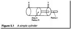
The basic linear actuator is the cylinder, or ram, shown in schematic form in Figure 5.1. Practical constructional details are dis cussed later. The cylinder in Figure 5.1 consists of a piston, radius R, moving in a bore. The piston is connected to a rod of radius r which drives the load. Obviously if pressure is applied to port X (with port Y venting) the piston extends. Similarly, if pressure is applied to port Y (with port Z venting), the piston retracts.
The force applied by a piston depends on both the area and the applied pressure. For the extend stroke, area A is given by 1rR2 . For a pressure P applied to port X, the extend force available is:
The units of expression 5.1 depend on the system being used. If SI units are used, the force is in newtons.
Expression 5.1 gives the maximum achievable force obtained with the cylinder in a stalled condition. One example of this occurs where an object is to be gripped or shaped.
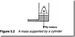
In Figure 5.2 an object of mass M is lifted at constant speed. Because the object is not accelerating, the upward force is equal to Mg newtons (in SI units) which from expression 5.1 gives the pressure in the cylinder. This is lower than the maximum system pressure; the pressure drop occurring across flow control valves and system piping. Dynamics of systems similar to this are discussed later.
When pressure is applied to port Y, the piston retracts. Total piston area here is reduced because of the rod, giving an annulus of area Aa where:
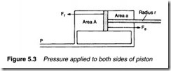
his is lower than the maximum extend force. In Figure 5.3 identical pressure is applied to both sides of a piston. This produces an
extend force Fe given by expression 5.1, and a retract force Fr given by expression 5.2. Because Fe is greater than Fr, the cylinder extends.
Normally the ratio NAa is about 6/5. In the cylinder shown in Figure 5.4, the ratio NAa of 2:1 is given by a large diameter rod. This can be used to give an equal extend and retract force when connected as shown. (The servo valve of Figure 4.40 also uses this principle.)
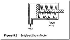
Cylinders shown so far are known as double-acting, because fluid pressure is used to extend and retract the piston. In some applications a high extend force is required (to clamp or form an object) but the retract force is minimal. In these cases a single acting cylinder (Figure 5.5) can be used, which is extended by fluid but retracted by a spring. If a cylinder is used to lift a load, the load itself can retract the piston.
Single-acting cylinders are simple to drive (particularly for pneumatic cylinders with quick exhaust valves (see Chapter 4)) but the
extend force is reduced and, for spring-return cylinders, the Figure length of the cylinder is increased for a given stroke to accommodate the spring.
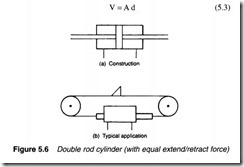
A double rod cylinder is shown in Figure 5.6a. This has equal fluid areas on both sides of the piston, and hence can give equal forces in both directions. If connected as shown in Figure 5.3 the piston does not move (but it can be shifted by an outside force). Double rod cylinders are commonly used in applications similar to Figure 5.6b where a dog is moved by a double rod cylinder acting via a chain.
The speed of a cylinder is determined by volume of fluid delivered to it. In the cylinder in Figure 5.7 the piston, of area A, has moved a distance d. This has required a volume V of fluid where:
The flow rate units of expression 5.4 depend on the units being used. If dis in metres, v in metres min- 1 and A in metres2, flow rate is in metres3 min- 1.
In pneumatic systems, it should be remembered, it is normal to express flow rates in STP (see Chapter 3). Expression 5.4 gives the fluid volumetric flow rate to achieve a required speed at working pressure. This must be normalised to atmospheric pressure by using Boyle’s law (given in expression 1.17).
The air consumption for a pneumatic cylinder must also be nor malised to STP. For a cylinder of stroke S and piston area A, nor malised air consumption is:
![]() where Pa is atmospheric pressure and Pw the working pressure. The repetition rate (e.g. 5 strokes min- 1) must be specified to allow mean air consumption rate to be calculated.
where Pa is atmospheric pressure and Pw the working pressure. The repetition rate (e.g. 5 strokes min- 1) must be specified to allow mean air consumption rate to be calculated.
It should be noted that fluid pressure has no effect on piston speed (although it does influence acceleration). Speed is deter mined by piston area and flow rate. Maximum force available is unrelated to flow rate, instead being determined by line pressure and piston area. Doubling the piston area while keeping flow rate and line pressure constant, for example, gives half speed but doubles the maximum force. Ways in which flow rate can be con trolled are discussed later.
Construction
Pneumatic and hydraulic linear actuators are constructed in a similar manner, the major differences arising out of differences in operating pressure (typically 100 bar for hydraulics and 10 bar for pneumatics, but there are considerable deviations from these values).
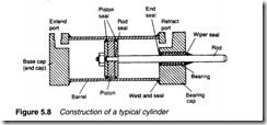
Figure 5.8 shows the construction of a double-acting cylinder. Five locations can be seen where seals are required to prevent leakage. To some extent, the art of cylinder design is in choice of seals, a topic discussed further in a later section.
There are five basic parts in a cylinder; two end caps (a base cap and a bearing cap) with port connections, a cylinder barrel, a piston and the rod itself. This basic construction allows fairly simple man ufacture as end caps and pistons are common to cylinders of the same diameter, and only (relatively) cheap barrels and rods need to be changed to give different length cylinders. End caps can be secured to the barrel by welding, tie rods or by threaded connection. Basic constructional details are shown in Figure 5.9.
The inner surface of the barrel needs to be very smooth to prevent wear and leakage. Generally a seamless drawn steel tube is used which is machined (honed) to an accurate finish. In applications
where the cylinder is used infrequently or may come into contact with corrosive materials, stainless steel, aluminium or brass tube may be used.
Pistons are usually made of cast iron or steel. The piston not only transmits force to the rod, but must also act as a sliding bearing in the barrel (possibly with side forces if the rod is subject to a lateral force) and provide a seal between high and low pressure sides. Piston seals are generally used between piston and barrel. Occasionally small leakage can be tolerated and seals are not used. A bearing surface (such as bronze) is deposited on to the piston surface then honed to a finish similar to that of the barrel.
The surface of the cylinder rod is exposed to the atmosphere when extended, and hence liable to suffer from the effects of dirt, moisture and corrosion. When retracted, these antisocial materials may be drawn back inside the barrel to cause problems inside the cylinder. Heat treated chromium alloy steel is generally used for strength and to reduce effects of corrosion.
A wiper or scraper seal is fitted to the end cap where the rod enters the cylinder to remove dust particles. In very dusty atmospheres external rubber bellows may also be used to exclude dust (Figure 5.9a) but these are vulnerable to puncture and splitting and need regular inspection. The bearing surface, usually bronze, is fitted behind the wiper seal.
An internal sealing ring is fitted behind the bearing to prevent high pressure fluid leaking out along the rod. The wiper seal, bearing and sealing ring are sometimes combined as a cartridge assembly to simplify maintenance. The rod is generally attached to the piston via a threaded end as shown in Figures 5.9b and c. Leakage can occur around the rod, so seals are again needed. These can be cap seals (as in Figure 5.9b) which combine the roles of piston and rod seal, or a static 0 ring around the rod (as in Figure 5.9c).
End caps are generally cast (from iron or aluminium) and incorporate threaded entries for ports. End caps have to withstand shock loads at extremes of piston travel. These loads arise not only from fluid pressure, but also from kinetic energy of the moving parts of the cylinder and load.
These end of travel shock loads can be reduced with cushion valves built into the end caps. In the cylinder shown in Figure 5.10, for example, exhaust fluid flow is unrestricted until the plunger
enters the cap. The exhaust flow route is now via the deceleration valve which reduces the speed and the end of travel impact. The deceleration valve is adjustable to allow the deceleration rate to be set. A check valve is also included in the end cap to bypass the deceleration valve and give near full flow as the cylinder extends. Cushioning in Figure 5.10 is shown in the base cap, but obviously a similar arrangement can be incorporated in bearing cap as well.
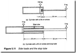
Cylinders are very vulnerable to side loads, particularly when fully extended. In Figure 5.1la a cylinder with a 30 em stroke is fully extended and subject to a 5 kg side load. When extended there is typically 1 em between piston and end bearing. Simple leverage will give side loads of 155 kg on the bearing and 150 kg on the piston seals. This magnification of side loading increases cylinder wear. The effect can be reduced by using a cylinder with a longer stroke, which is then restricted by an internal stop tube as shown in Figure 5. lib.
The stroke of a simple cylinder must be less than barrel length, giving at best an extended/retracted ratio of 2:1. Where space is restricted, a telescopic cylinder can be used. Figure 5.12 shows the construction of a typical double-acting unit with two pistons. To extend, fluid is applied to port A. Fluid is applied to both sides of
piston 1 via ports X and Y, but the difference in areas between sides of piston 1 causes the piston to move to the right.
To retract, fluid is applied to port B. A flexible connection is required for this port. When piston 2 is driven fully to the left, port Y is now connected to port B, applying pressure to the right-hand side of piston 1 which then retracts.
The construction of telescopic cylinders requires many seals which makes maintenance complex. They also have smaller force for a given diameter and pressure, and can only tolerate small side loads.
Pneumatic cylinders are used for metal forming, an operation requiring large forces. Pressures in pneumatic systems are lower than in hydraulic systems, but large impact loads can be obtained by accelerating a hammer to a high velocity then allowing it to strike the target.
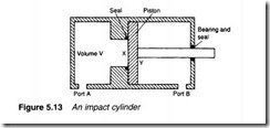
Such devices are called impact cylinders and operate on the principle illustrated in Figure 5.13. Pressure is initially applied to port
B to retract the cylinder. Pressure is then applied to both ports A and B, but the cylinder remains in a retracted state because area X is less than area Y. Port B is then vented rapidly. Immediately, the full piston area experiences port A pressure. With a large volume of gas stored behind the piston, it accelerates rapidly to a high velocity (typically lOrn s-1).
