In Chap. 1 we defined fluid mechanics as the science that deals with the behavior of fluids at rest or in motion, and the interaction of fluids with solids or other fluids at the boundaries. There is a wide variety of fluid flow problems encountered in practice, and it is usually convenient to classify them on the basis of some common characteristics to make it feasible to study them in groups. There are many ways to classify the fluid flow problems, and here we present some general categories.
Viscous versus Inviscid Regions of Flow
When two fluid layers move relative to each other, a friction force develops between them and the slower layer tries to slow down the faster layer. This internal resistance to flow is called the viscosity, which is a measure of internal stickiness of the fluid. Viscosity is caused by cohesive forces between the molecules in liquids, and by molecular collisions in gases. There is no fluid with zero viscosity, and thus all fluid flows involve viscous effects to some degree. Flows in which the effects of viscosity are significant are called viscous flows. However, in many flows of practical interest, there are regions (typically regions not close to solid surfaces) where viscous forces are negligibly small compared to inertial or pressure forces. Neglecting the viscous terms in such inviscid flow regions greatly simplifies the analysis without much loss in accuracy.
Internal versus External Flow
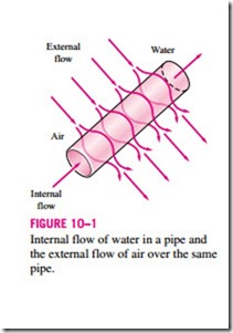
A fluid flow is classified as being internal or external, depending on whether the fluid is forced to flow in a confined channel or over a surface. The flow of an unbounded fluid over a surface such as a plate, a wire, or a pipe is external flow. The flow in a pipe or duct is internal flow if the fluid is completely bounded by solid surfaces. Water flow in a pipe, for example, is internal flow, and airflow over an exposed pipe during a windy day is ex- ternal flow (Fig. 10–1). The flow of liquids in a duct is called open-channel flow if the duct is only partially filled with the liquid and there is a free sur- face. The flow of water in rivers and irrigation ditches are examples of such flows.
Compressible versus Incompressible Flow
A fluid flow is classified as being compressible or incompressible, depending on the density variation of the fluid during flow. The densities of liquids are essentially constant, and thus the flow of liquids is typically incompressible. Therefore, liquids are usually classified as incompressible substances. A pressure of 210 atm, for example, causes the density of liquid water at 1 atm to change by just 1 percent. Gases, on the other hand, are highly compressible. A
pressure change of just 0.01 atm, for example, causes a change of 1 percent in the density of atmospheric air. However, gas flows can be treated as incompressible if the density changes are under about 5 percent, which is usually the case when the flow velocity is less than 30 percent of the speed of sound in that gas (i.e., the Mach number of flow is less than 0.3). The speed of sound in air at room temperature is 346 m/s. Therefore, the compressibility effects of air can be neglected at speeds under about 100 m/s. Note that the flow of a gas is not necessarily a compressible flow.
Small density changes of liquids corresponding to large pressure changes can still have important consequences. The irritating “water hammer” in water pipes, for example, is caused by the vibrations of the pipe generated by the reflection of pressure waves following the sudden closing of the valves.
Laminar versus Turbulent Flow
Some flows are smooth and orderly while others are rather chaotic. The highly ordered fluid motion characterized by smooth streamlines is called laminar. The flow of high-viscosity fluids such as oils at low velocities is typically laminar. The highly disordered fluid motion that typically occurs at high velocities and is characterized by velocity fluctuations is called turbulent. The flow of low-viscosity fluids such as air at high velocities is typically turbulent. The flow regime greatly influences the required power for pumping.
Natural (or Unforced) versus Forced Flow
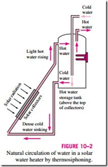
A fluid flow is said to be natural or forced, depending on how the fluid motion is initiated. In forced flow, a fluid is forced to flow over a surface or in a pipe by external means such as a pump or a fan. In natural flows, any fluid motion is due to natural means such as the buoyancy effect, which manifests itself as the rise of the warmer (and thus lighter) fluid and the fall of cooler (and thus denser) fluid. This thermosiphoning effect is commonly used to replace pumps in solar water heating systems by placing the water tank sufficiently above the solar collectors (Fig. 10–2).
Steady versus Unsteady Flow
The terms steady and uniform are used frequently in engineering, and thus it is important to have a clear understanding of their meanings. The term steady implies no change at a point with time. The opposite of steady is unsteady. The term uniform implies no change with location over a specified region. These meanings are consistent with their everyday use (steady girlfriend, uniform distribution, etc.).
The terms unsteady and transient are often used interchangeably, but these terms are not synonyms. In fluid mechanics, unsteady is the most general term that applies to any flow that is not steady, but transient is typically used for developing flows. When a rocket engine is fired up, for example, there are transient effects as the pressure builds up inside the rocket engine, the flow accelerates, etc., until the engine settles down and operates steadily. The term periodic refers to the kind of unsteady flow in which the flow oscillates about a steady mean.
Many devices such as turbines, compressors, boilers, condensers, and heat exchangers operate for long periods of time under the same conditions, and they are classified as steady-flow devices. (Note that the flow field near the
rotating blades of a turbomachine is of course unsteady, but we consider the overall flow field rather than the details at some localities when we classify devices.) During steady flow, the fluid properties can change from point to point within a device, but at any fixed point they remain constant. Therefore, the volume, the mass, and the total energy content of a steady-flow device or flow section remain constant in steady operation.
Steady-flow conditions can be closely approximated by devices that are in- tended for continuous operation such as turbines, pumps, boilers, condensers, and heat exchangers of power plants or refrigeration systems. Some cyclic de- vices, such as reciprocating engines or compressors, do not satisfy the steady- flow conditions since the flow at the inlets and the exits is pulsating and not steady. However, the fluid properties vary with time in a periodic manner, and the flow through these devices can still be analyzed as a steady-flow process by using time-averaged values for the properties.
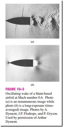
Some fascinating visualizations of fluid flow are provided in the book An Album of Fluid Motion by Milton Van Dyke (1982). A nice illustration of an unsteady-flow field is shown in Fig. 10–3, taken from Van Dyke’s book. Fig- ure 10–3a is an instantaneous snapshot from a high-speed motion picture; it reveals large, alternating, swirling, turbulent eddies that are shed into the periodically oscillating wake from the blunt base of the object. The eddies pro- duce shock waves that move upstream alternately over the top and bottom surfaces of the airfoil in an unsteady fashion. Figure 10–3b shows the same flow field, but the film is exposed for a longer time so that the image is time averaged over 12 cycles. The resulting time-averaged flow field appears “steady” since the details of the unsteady oscillations have been lost in the long exposure.
One of the most important jobs of an engineer is to determine whether it is sufficient to study only the time-averaged “steady” flow features of a problem, or whether a more detailed study of the unsteady features is required. If he or she were interested only in the overall properties of the flow field, such as the time-averaged drag coefficient, the mean velocity and pressure fields, etc., a time-averaged description like that of Fig. 10–3b, time-averaged ex- perimental measurements, or an analytical or numerical calculation of the time-averaged flow field would be sufficient. However, if he or she were interested in details about the unsteady-flow field, such as flow induced vibrations, unsteady pressure fluctuations, or the sound waves emitted from the turbulent eddies or the shock waves, a time-averaged description of the flow field would be insufficient.
Most of the analytical and computational examples provided in this text- book deal with steady or time-averaged flows, although we occasionally point out some relevant unsteady-flow features as well when appropriate.
One-, Two-, and Three-Dimensional Flows
A flow field is best characterized by the velocity distribution, and thus a flow is said to be one-, two-, or three-dimensional if the flow velocity varies in one, two, or three primary dimensions, respectively. A typical fluid flow involves a three-dimensional geometry and the velocity may vary in all three dimensions
rendering the flow three-dimensional [“V (x, y, z) in rectangular or “V (r, u, z) in cylindrical coordinates]. However, the variation of velocity in certain directions can be small relative to the variation in other directions, and can be ignored with negligible error. In such cases, the flow can be modeled conveniently as being one- or two-dimensional, which is easier to analyze.
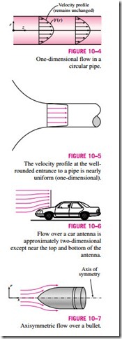
When the entrance effects are far upstream of the region of interest, fully developed fluid flow in a circular pipe is one-dimensional since the velocity r z varies in the radial r-direction but not in the angular u- or axial z-directions (Fig. 10–4). That is, the velocity profile is the same at any axial z-location, and it is symmetric about the axis of the pipe. Note that even in this simple flow, the velocity cannot be uniform across the cross section of the pipe be- cause of the no-slip condition. However, at a well-rounded entrance to the pipe, the velocity profile may be approximated as nearly uniform across the pipe, since the velocity is constant at all radii except very close to the pipe wall (Fig. 10–5)
A flow may be approximated as two-dimensional when the aspect ratio is large and the flow does not change appreciably along the longer dimension. For example, the flow of air over a car antenna can be considered two- dimensional except near its ends since the antenna’s length is much greater than its diameter, and the airflow hitting the antenna is fairly uniform (Fig. 10–6).
