Pressure regulation
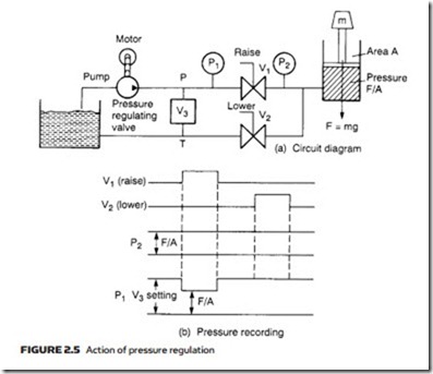
Figure 2.5a shows the by now familiar system where a load is raised or lowered by a hydraulic cylinder. With valve V1 open, fluid flows from the pump to the cylinder, with both pressure gauges P1 and P2 indicating a pressure of F/A. With valves V1 closed and V2 open, the load falls with fluid being returned to the tank. With the load falling, gauge P2 will still show a pressure of F/A, but at P1 the pump is dead-ended, leading to a continual increase in pressure as the pump delivers fluid into the pipe.
Obviously some method is needed to keep P1 at a safe level. To achieve this, pressure-regulating valve V3 has been included. This is normally closed (no connection between P and T) while the pressure is below some preset level
(called the cracking pressure). Once the cracking pressure is reached valve V3 starts to open, bleeding fluid back to the tank. As the pressure increases, valve V3 opens more until, at a pressure called the full flow pressure, the valve is fully open. With valve V1 closed, all fluid from the pump returns to the tank via the pressure-regulating valve, and P1 settles somewhere between the cracking and full flow pressures.
Cracking pressure of a relief valve must be higher than a system’s working pressure, leading to a fall in system pressure as valve V1 opens and external work is performed. Valve positions and consequent pressure readings are shown in Figure 2.5b.
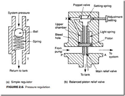
The simplest form of pressure regulation valve is the ball and spring ar- rangement of Figure 2.6a. System pressure in the pipe exerts a force of P × a on the ball. When the force is larger than the spring compressive force the valve will crack open, bypassing fluid back to the tank. The higher the pipe pressure, the more the valve opens. Cracking pressure is set by the spring compression and in practical valves this can be adjusted to suit the application.
The difference between cracking and full flow pressure is called the pressure override. The steady (non-working) system pressure will lie somewhere within the pressure override, with the actual value determined by pipe sizes and char- acteristics of the pressure-regulating valve itself.
If the quiescent pressure is required to be precisely defined, a small pressure override is needed. This pressure override is related to spring tension in a simple relief valve. When a small, or precisely defined, override is required, a balanced piston relief valve (shown in Figure 2.6b) is used.
The piston in this valve is free moving, but is normally held in the lowered position by a light spring, blocking flow to the tank. Fluid is permitted to pass to the upper chamber through a small hole in the piston. The upper chamber is sealed by an adjustable spring-loaded poppet. In the low-pressure state, there is no flow past the poppet, so pressures on both sides of the piston are equal and spring pressure keeps the valve closed.
When fluid pressure rises, the poppet cracks and a small flow of fluid passes from the upper chamber to the tank via the hole in the piston center. This fluid is replenished by fluid flowing through the hole in the piston. With fluid flow there is now a pressure differential across the piston, which is acting only against a light spring. The whole piston lifts, releasing fluid around the valve stem until a balance condition is reached. Because of the light-restoring spring a very small override is achieved.
The balanced piston relief valve can also be used as an unloading valve. Plug X is a vent connection and, if removed, fluid flows from the main line through the piston. As before, this causes the piston to rise and flow to be dumped to the tank. Controlled loading/unloading can be achieved by the use of a finite posi- tion valve connected to the vent connection.
When no useful work is being performed, all fluid from the pump is pressur- ized to a high pressure then dumped back to the tank (at atmospheric pressure) through the pressure-regulating valve. This requires motor power defined earlier by expressions 2.3 and 2.4, and represents a substantial waste of power. Less obviously, energy put into the fluid is converted to heat, leading to a rise in fluid temperature. Surprisingly, motor power will be higher when no work is being done because cracking pressure is higher than working pressure.
This waste of energy is expensive, and can lead to the need for heat exchangers to be built into the tank to remove the excess heat. A much more economic arrange- ment uses loading/unloading valves, a topic discussed further in a later section.

