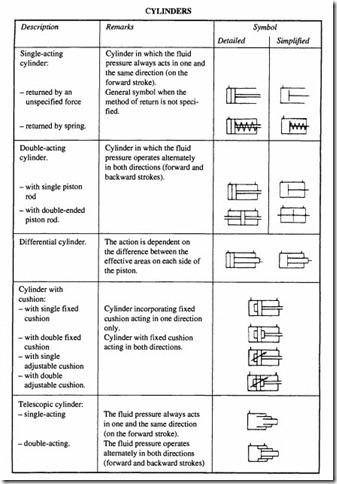
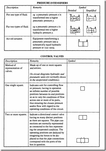
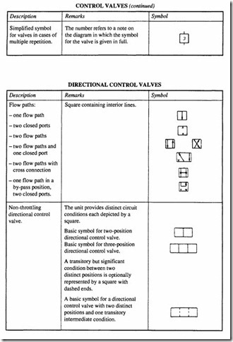
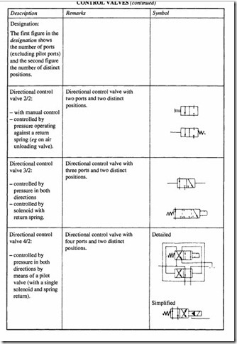
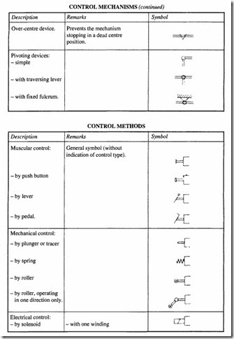
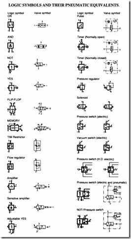
Graphical symbols for pneumatic systems and components
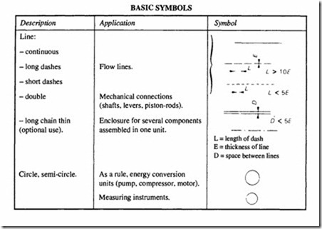
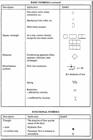
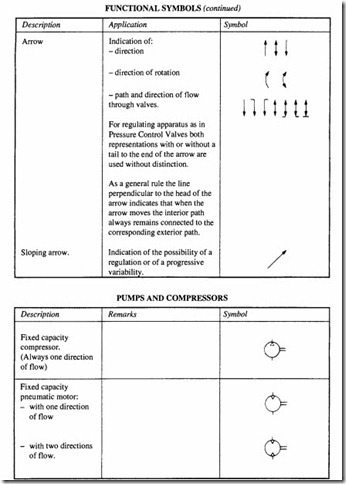
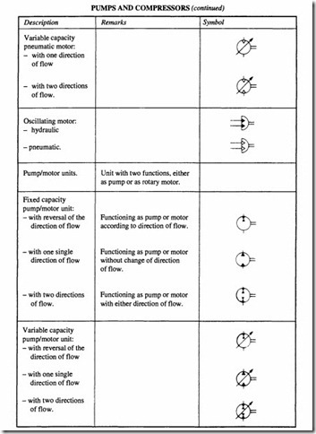
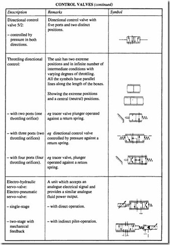
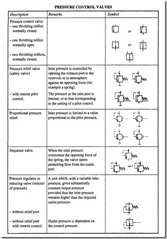
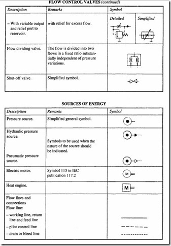
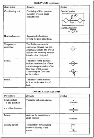
The following symbols are specified in BS 2917 (ISO 1219)
General symbols (basic and functional)
The symbols for hydraulic and pneumatic equipment and accessories are functional and consist of one or more basic symbols and one or more functional symbols. They are neither to scale nor oriented in any particular direction.
CETOP recommendations for circuit diagrams
The following rules and recommendations are extracted from CETOP RP41 -Hydraulic and Pneumatic Systems Circuit Diagrams. The purpose of this document is to facilitate the design, construction, description and maintenance of fluid power systems by aiding communication through uniform presentation. The following recommendations are based on the appropriate CETOP documents and applicable ISO standards (mostly adopted as British Standards). It is not necessary for a circuit diagram to incorporate all the requirements listed but anything which is shown must be in accordance with the appropriate section. They apply generally to all fluid power systems.
Design of circuit diagrams
The circuit diagram must show fluid circulation for all the control and motion functions. All hydraulic and pneumatic components and flow line junctions in the plant will be represented functionally. In addition all control components that affect the operational processes of the fluid power system will be shown.
The circuit diagram need not be constructed with reference to the physical arrangement of the system. Interdependent circuits should be shown on one diagram. For electro hydraulic or electro-pneumatic controls, the circuit diagram will however be divided into one hydraulic and one pneumatic circuit diagram and if necessary a separate electrical circuit.
The following circuit diagram formats should be used:
• ISO A format.
Length preferably 297 mm, exceptionally 420 or 594 mm. Width up to 1189 mm.
• Diagrams will be folded to ISO A format with a binding margin (except for diagrams for reproduction).
• The layout of the circuit diagram must be clear. Care should be taken to see that the circuit paths are easily followed. Pneumatic circuits should be drawn if possible in the sequence of the operational process of functions. The components of the individual control chains and groups should be shown wherever possible in the direction of energy flow.
• Cylinders and directional control valves should preferably be shown horizontally.
Fluid lines should be represented wherever possible by straight lines without intersections.
• The location of control components such as sequence switch cams and simple cams should be indicated. Ifa signalling element is to be actuated by a one-way trip, then the actuating direction will be indicated by an arrow. In the case of electro hydraulic and electro-pneumatic control systems, signalling and final control elements such as limit switches and electro-magnetic valves will be shown in both circuit diagrams.
• Individual sub-circuits may be identified. The function of each operating element should be indicated beside it (for example clamping or lifting). Where necessary for a better understanding, a function chart can be drawn up. Components should be drawn up in accordance with ISO 1219 (BS 2917) for fluid power equipment. Where no symbol exists, the operation of the part should be clearly shown by means of a simplified sectional representation, or the like.
• Symbols that are repeated in the diagram can be represented by a numbered rectangle and the corresponding symbols shown separately.
Data to go on circuit diagram
Every component must be clearly identified by an item number. Components in a given sub-circuit may be given a common prime identification plus a running sub-number, for example sub-circuit 2, component 3 = 2.3.
Component operating positions
In the case of valves with discrete switching positions, these positions may be identified by letter, the letter ‘0’ being used only for spring return positions (spring-loaded valves).
Identification of ports
Ports will be identified on the circuit diagram by the characters marked on the components of the connection plate. This applies to individual components and sub-assemblies.
Identification of oil or air lines
The pipelines are to be drawn according to their function in line with BS 2917.
In cases where hydraulic and pneumatic circuits are represented on one diagram, they should be identified in accordance with BS 2917.
Should it be necessary to identify the pipelines more precisely, the following code applies:
