High pressure conveying – Part IV
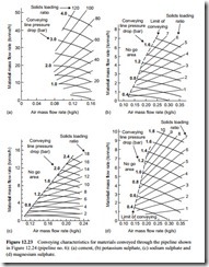
To complete the high pressure illustrations of material conveying characteristics four materials conveyed through a 95 m long pipeline of 81 mm bore are presented in Figure 12.23. With a longer pipeline the pressure gradient available for conveying is limited and with a larger bore line the air flow rate requirements are also very different.
Cement
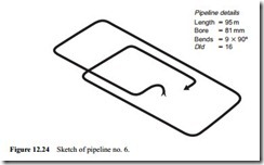
The conveying characteristics for the cement were presented by way of illustration in the previous chapter with Figure 11.7a and are produced here in Figure 12.23a for comparison purposes. All four materials were conveyed through the pipeline shown earlier in Figure 11.2 and this is reproduced here in Figure 12.24 as pipeline no. 6 for reference.
The cement could be conveyed in dilute phase with a conveying line inlet air vel- ocity of about 11 m/s but once again this is an insignificant part of the conveying char- acteristics since air supply pressures of 4 bar gauge were able to be used for conveying
the material. With high pressure air the cement could be conveyed quite reliably with conveying line inlet air velocities down to 3 m/s and so solids loading ratios of over 100 were achieved. Although the air supply pressure was high, the air flow rate required was relatively low since the air velocity required for conveying was low. As a consequence the air flow rate axis is only taken to 0.16 kg/s. The material flow rate
axis is taken to 50 tonne/h and shows the potential capability of small bore pipelines for the conveying of this type of material.
Potassium sulphate
The conveying characteristics for the potassium sulphate are presented in Figure 12.23b. The minimum conveying air velocity was about 14 m/s and the material conveyed very well, but the conveying capability of the material, in terms of tonne/h, is probably the poorest of any presented here. With a conveying line pressure drop of 1.8 bar the solids loading ratio was only about seven, with just 7 tonne/h conveyed.
The conveying characteristics for potassium chloride, conveyed through this same pipeline, were presented in Figure 11.5b and 7 tonne/h was conveyed with a conveying line pressure drop of only 1.0 bar and the minimum conveying air velocity was 15 m/s.
Sodium sulphate
The conveying characteristics for sodium sulphate are presented in Figure 12.23c. This is a ground grade of the material. The material had a low minimum value of convey- ing air velocity at about 11 m/s, and this is why it was possible to convey the material with a conveying line pressure drop of 2.4 bar and achieve a solids loading ratio of 18, but there was no possibility of the material being conveyed in dense phase.
Magnesium sulphate
The conveying characteristics for magnesium sulphate are presented in Figure 12.23d. This material had a mean particle size of about 225 j.Lm and the minimum conveying air velocity was about 14 m/s. The bulk density of the material was about 1020 kg/m3 and the particle density 2350 kg/m3. The conveying capability was similar to that of the sodium sulphate, but as the conveying line inlet air velocity was so much higher the maximum value of solids loading ratio achieved was only about 10.

