Regulating valves
An important item in a compressed air layout is a regulating valve which ensures that the pressure in the system (or a part of the system) is not exceeded. The first important function of these valves is for safety: the pipes, receiver and other items in the layout have a maximum operating pressure, which if exceeded could cause damage and eventually, if the pressure were allowed to increase indefinitely, result in an explosion. The second function is to provide for a part of the system to operate at a lower pressure than the main supply, eg for operating a blow gun, for paint spraying, for pneumatic sensing and for applying a known force to an air cylinder. A well designed valve must maintain a constant pressure despite changes in the primary pressure and the flow rate.
The compressor will normally incorporate its own unloading system which ensures that it operates at a condition which maintains the design system pressure. Further control may be required outside the compressor unit; regulating valves described in this chapter provide that control.
There are various types of regulating valves. Reference should be made to ISO 4 I26, Safety Valves – Control Requirements, for a full set of definitions, from which the following are derived:
Back pressure regulator. A valve having its inlet port connected to the system so that by automatic adjustment of its outlet flow, the system pressure remains substantially constant. System pressure must remain higher than the preset opening pressure of the valve. Under normal operating conditions the valve may be continuously flowing to waste.
Pressure reducing valve. A valve having its outlet port connected to the system so that with varying inlet pressure or outlet flow, the outlet pressure remains substantially constant. Inlet pressure must remain substantially higher than the selected outlet pressure.
Pressure relief valve. A valve having its inlet port connected to the system which limits the maximum pressure by exhausting fluid when the system pressure exceeds the preset pressure of the valve. Under normal operating conditions the valve remains closed, only operating when unusual system conditions prevail.
Safety valve. A name given to a type of pressure relief valve which protects the system from over-pressurisation in the event of a malfunction of a component forming part of the system. It opens and exhausts fluid when the system pressure exceeds its design pressure by a selected amount. The valve is required to have a certified flow capacity sufficient to prevent the system pressure exceeding its design pressure by more than a stipulated percentage or amount, usually 10% or 0.3 bar, whichever is the greater. Under normal conditions a safety valve remains closed and in the event of its functioning, the cause should be established before the system is put back into operation.
Safety lock up valve. A valve with its inlet port connected to one part of the system so that should the inlet pressure fall below a preset amount the valve will close to Jock a minimum pressure in that part of the system connected to the outlet port.
Sequence valve. A valve with its inlet port connected to one part of the system and its outlet port connected to another part of the system and set so that until the inlet pressure rises above the preset opening pressure the fluid medium is prevented from flowing to the outlet port.
Types of pressure relief valves
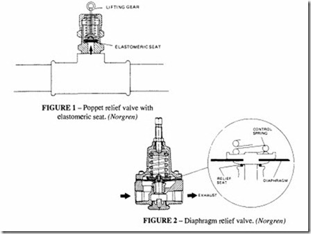
A direct loaded relief valve is one in which the loading due to the fluid pressure is opposed by direct mechanical loading such as spring; weight loading is rarely found in compressed air systems. Direct loaded valves can be either poppet valves in which the sealing member is directly loaded onto a seat by the spring and the system pressure acts directly on the
seating member (Figure 1), or diaphragm valves in which the spring acts against a diaphragm exposed to the system pressure (Figure 2).
Poppet valves suffer from serious drawbacks. Their performance is inconsistent due to “stiction”, they are insensitive because of the small seat areas and they have a limited flow capacity. Diaphragm operated valves eliminate some of the drawbacks of the simple poppet valves: because pressure is sensed over a larger area (that of the diaphragm) they are more sensitive and have a larger flow capacity. However direct operated diaphragm valves still have performance limitations, due to the size of the diaphragm in relation to the spring loading.
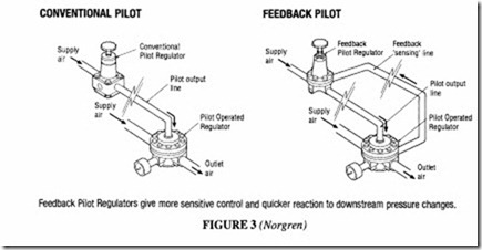
Most modern pressure relief valves, at least in the larger sizes, are pilot valves, of which there are two varieties. A ‘pilot controlled relief valve’ is a valve in which the loading spring is replaced by fluid pressure from a control pilot; the pilot pressure comes from a pressure regulator which is remote from the relief valve and has its own supply which may be independent of the main supply, see Figure 3. A ‘pilot operated relief valve’, usually a diaphragm type, is one in which a small integral spring-operated valve controls the opening of the main valve; system pressure normally keeps the main valve closed and no external supply is needed.
Pilot controlled relief valves have superior characteristics to those of direct spring systems. Pressure is applied to the control side of the diaphragm from a pilot regulator. A small bleed is necessary to prevent control variations due to temperature fluctuations. Relief valves controlled by pilot regulators do have shortcomings when used for system relief, but they are useful when the control has to come from a separate supply or when the relief pressure needs to be altered from time to time; a pressure gauge can be incorporated in the pilot line for pressure setting purposes. Unfortunately regulators are not fail-safe and if one has to incorporate another relief valve in the pilot line, the whole circuit becomes very complicated.
The integral pilot operated relief valve is now the one most commonly used. This is really two valves in one body: the relief pressure is set by the spring load on the pilot relief
Operation
The unit has a main valve assembly (A) and an integral pilot assembly (8). The main valve assembly (A) incorporates a small orifice to allow air to reach the pilot diaphragm (8).
Primary air enters the inlet port, passes through the restrictor in the main valve assembly (A) and reaches the pilot diaphragm (8).1fthe pressure under the pilot diaphragm is sufficient to overcome the set spring pressure, the pilot valve will open and air will exhaust through the bonnet holes (C). This will cause the pressure above the main valve assembly (A) to drop creating a pressure differential across the diaphragm of the valve assembly. The main valve will now open and air will exhaust through the relief port (D). The desired relief pressure is set using the adjusting screw (E).
VVhen the excess pressure has been exhausted, the spring force acting on the pilot assembly (8) will close the pilot valve. This will cause the air pressure above the main valve assembly (A) to build up and this, in turn, will close the main valve and prevent further escape of air.
valve; the spring load is easily changed by adjusting a screw on the pilot valve. It can be seen from Figure 4 that, over its operating range, the pressure remains practically constant; such characteristics are greatly superior to a simple directly operated valve.
Installation considerations
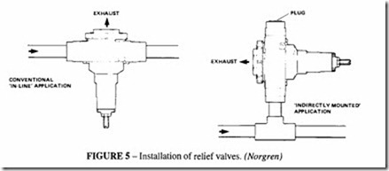
Pilot operated relief valves are intended for in-line installation, but can also be used indirectly mounted, Figure 5. A relief valve must be selected to pass the maximum flow rate of the compressor or other source of air, but a valve of this calculated size may not conveniently fit into the main line, which will probably be of a larger bore. To install a small valve in a larger pipe will introduce an excessive pressure drop, so an indirectly mounted valve will be appropriate.
A typical example of excess pressure control is where a relief valve is included between the compressor and receiver to protect the receiver should the control system of the compressor fail. Sizing such a valve is fairly easily done, because the maximum flow rate of the compressor is known, but there may be difficulties in determining the size of a relief valve to install in a branch line. Usually the flow rate required in a branch is a small proportion of the total possible flow, yet if there is a failure of one of the control valves, such as a pressure regulator, the whole of the compressor output may try to pass through the branch. It would be uneconomic either to install a full-flow relief valve at every point in a system where protection was needed or to make every system component capable of resisting the maximum pressure.
There are several ways of dealing with this difficulty: one way would be to ensure that a restriction is inserted in the branch to limit the flow and use the orifice flow to size the relief valve; another way is determine the failure flow of the pressure regulator and size the valve to that. A third way, if the failure flow is unknown, is to take an orifice of one half the supply pipe size of the regulator, double the maximum orifice flow at the supply pressure and use that to size the relief valve. For example if a G’h regulator is used to control a supply pressure of 6 bar, the failure flow is taken as twice the flow through a
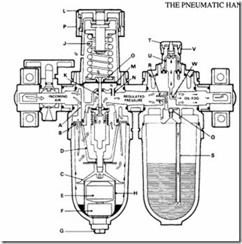
As compressed air passes through the shut-off valve and enters the filter section (A) it passes through the directional louvres (B) forcing it into a whirling flow pattern. Liquid particles and heavy solids are thrown against the inside wall of the bowl by centrifugal force. The liquid then runs to the bottom of the bowl where it is either removed by the automatic drain assembly or by the manual drain. The baffle (C) maintains a ‘quiet zone’ in the lower portion of the bowl to prevent air turbulence from picking up the liquid and returning it to the air stream. The air then passes through the filter element (D) to remove solid contaminants. The automatic drain assembly dumps the liquid as it collects. As the liquid builds up in the bowl the float (E) rises, causing the piston type automatic-drain assembly (F) to open and release the liquid under pressure. The drain mechanism is protected by a protective screen (H). From the filter, the compressed air goes to the regulator section.
When no load is applied to the adjusting spring (J), the regulator valve (K) is closed. As the knob (L) is turned, it applies a load to the spring which is transmitted to the valve through the flexible diaphragm (M) opening the valve. The air pressure side of the diaphragm is connected to the regulator outlet by syphon tube (N) so that regulated pressure is exerted against the diaphragm. As ttie regulated pressure increases, the pressure against the diaphragm increases, forcing the diaphragm to compress the adjusting spring until the load exerted by the spring is equal to the load exerted by the regulated pressure. Excess downstream pressure is vented through relief seat (0). The pressure setting can be locked with the snap action lock (P).
As the filtered and regulated air enters the lubricator a portion of it flows through the check valve (Q) to pressurize the bowl. The major portion of the incoming air flows through the lubricator past the flow sensor (R) which allows the lubricator to automatically maintain a constant oil density.
The combination of the pressurized oil reservoir and the pressure differentical created at the flow sensor causes the oil to flow up the syphon tube (S). The drip rate can be set by adjusting knob (T) as it flows through the sight-feed dome (U). The setting can be locked with snap action ring (V).
All oil passing through the sight-feed dome to the orifice (W) is converted to constant density fog and continues downstream to the point of application.
approach the manufacturers who should be able to quote the failure rates of their valves. If the constructional details are known, it may be possible to determine the equivalent orifice size by examination.
Care should be taken when siting a relief valve. Although it may not operate often, when it does it should not discharge a high pressure stream in a direction that may affect personnel or blow dirt, dust or other objects around; if possible it should be sited at high level away from personnel, or there should be an exhaust pipe leading the flow away. Tamper proof covers are available to cover the case of unauthorised adjustment of the relief setting. Silencers are available to fit the exhaust port.
Pressure reducing valves
In a complex compressed air system there are likely to be several sub-systems or branch lines that need to have a pressure limitation, lower than the main pressure, placed on them. Too high a pressure can result in energy wastage, and many tools and other equipment either work best (or only) at their design pressure.
A pressure reducing valve (commonly known as a pressure regulator) is used in these circumstances. It reduces a high variable primary pressure to a lower, constant secondary pressure; it measures and corrects deviations in pressure. A regulator should also include a bleed so that if the secondary pressure exceeds the setting of the valve, the excess pressure can escape. A regulating valve must possess certain characteristics for reliable operation. The valve must be fitted with a balanced poppet valve otherwise pressure fluctuations will cause instability. The controlled pressure must be practically constant for all flow rates up to the rated maximum.
It is customary to install a combined assembly of filter regulator and lubricator (FRL) to filter out the free water droplets, then control the pressure and finally lubricate the controlled air. This assembly is used to supply regulated air to a branch of the main supply. It is usually built up in modular form and available in this form from a number of manufacturers. Not all elements of the assembly are required in every case. Thus for example if the air has already been filtered and the moisture removed, there is no need for an additional filter. A commonly available modular unit is a combined filter and regulator, the function of which is shown in Figure 6, which also includes a description of a micro lubricator. A filter regulator of this kind should also incorporate a pressure gauge to assist in setting the spring pre-load. The bowls of the filter and lubricator are often made of a transparent plastic, so that a visual check can be kept on the amount of the moisture and the lubricant. A metal safety guard can be fitted to enclose the polycarbonate bowl and all metal equipment is also available. It is better, if the installation permits it, to have an automatic drain on the filter bowl, which then allows the fitting of a safer metal bowl.
Electronically-set pressure regulators are available for remote control of the pressure.


