Hollow fibre filter
Hollow fibres were originally developed for dialysis and have now been adapted for compressed air. The filter is arranged with a smaller spread of hole sizes, but with a larger number of membranes. This gives a greater retention ability. Due to a closer pore distribution than conventional membrane filters, the number of pores per unit area of filter is greater, which extends the service life. A closer pore distribution means that the largest pore size is much reduced. A conventional membrane filter has a pore size at least 0.3 micron larger than a hollow fibre filter.
The development of a membrane filter element with a rated pore size ofO.I micron and a reduced pore distribution means the difference between the retention of viruses and bacteria. The construction of the hollow fibre filter means that it is economical to manufacture smaller elements for laboratory use.
Housings
Sterile filter cartridges must be fitted into a pressure holding housing. The method of sealing is by single or double 0-ring seals which allow sealing and movement during steam sterilization or shock loading without breaking the seal. Compressed air steriliza tion filter housings need to be designed to protect the filter cartridge from stress. Stainless steel housings are the usual choice of material; they should be electrolytically polished inside and out, and have no grooves or corners in which micro-organisms can collect. They should incorporate an automatic condensate drain. For economy, sterile filters can be made of gal vanised steel housings with stainless steel parts in contact with the compressed air or with a corrosion resistant coating. Aluminium housings with powder coated protection are also available.
Filter selection
Filters are sized according to the flow rate versus pressure drop information supplied by the manufacturer. A sterile filter has an initial pressure drop of about 0.1 bar although the rating can be reduced if necessary to meet the requirements of the process; a pressure drop
of about 0.2 bar is indicative of dirt collecting in the filter and it must be replaced. A pre filter should normally be incorporated in the circuit to reduce the load on the sterile filter. Coalescing type pre-filters can sustain a high pressure drop but it is normal to replace the element between 0.3 and 0.6 bar.
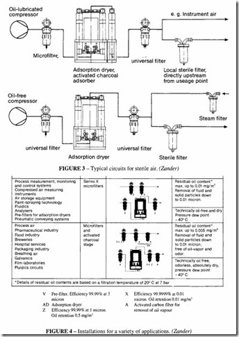
A complete filter assembly for producing sterile air will contain a number of separate elements. If the sterile supply is to be taken from a larger system with a variety of applications, an oil lubricated compressor may be the source of air; in this case an activated carbon filter will need to be incorporated. If all the air in the process needs to be sterile, then an oil-free compressor is probably the better choice. Figures 3 and 4 show some of the possible choices.
A decision has to be made about the criterion for replacement of the filter element. It is usual to replace the element after the recommended number of sterilization cycles, unless the pressure drop appears to be excessive. Provided that an adequate level of pre filtering is incorporated, pressure drop should not normally be the criterion.
