THE MANOMETER
We notice from Eq. 2–24 that an elevation change of z of a fluid corresponds to P/rg, which suggests that a fluid column can be used to measure pressure differences. A device based on this principle is called a manometer, and it is commonly used to measure small and moderate pressure differences. A manometer mainly consists of a glass or plastic U-tube containing one or more fluids such as mercury, water, alcohol, or oil. To keep the size of the manometer to a manageable level, heavy fluids such as mercury are used if large pressure differences are anticipated.
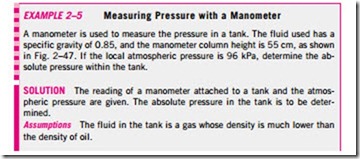
Consider the manometer shown in Fig. 2–46 that is used to measure the pressure in the tank. Since the gravitational effects of gases are negligible, the pressure anywhere in the tank and at position 1 has the same value. Further- more, since pressure in a fluid does not vary in the horizontal direction within a fluid, the pressure at point 2 is the same as the pressure at 1, P2 = P1.
The differential fluid column of height h is in static equilibrium, and it is open to the atmosphere. Then the pressure at point 2 is determined directly from Eq. 2–25 to be
where r is the density of the fluid in the tube. Note that the cross-sectional area of the tube has no effect on the differential height h, and thus the pressure exerted by the fluid. However, the diameter of the tube should be large enough (more than a few millimeters) to ensure that the surface tension effect and thus the capillary rise is negligible.
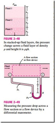
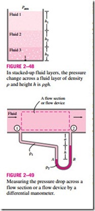
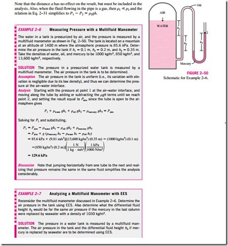
Many engineering problems and some manometers involve multiple immisciple fluids of different densities stacked on top of each other. Such systems can be analyzed easily by remembering that (1) the pressure change across a fluid column of height h is !1P = rgh, (2) pressure increases down- ward in a given fluid and decreases upward (i.e., Pbottom > Ptop), and (3) two points at the same elevation in a continuous fluid at rest are at the same pressure.
The last principle, also known as Pascal’s law, allows us to “jump” from one fluid column to the next in manometers without worrying about pressure change as long as we don’t jump over a different fluid, and the fluid is at rest. Then the pressure at any point can be determined by starting with a point of known pressure, and adding or subtracting rgh terms as we advance toward the point of interest. For example, the pressure at the bottom of the tank in Fig. 2–48 can be determined by starting at the free surface where the pressure is Patm, and moving downward until we reach point 1 at the bottom, and setting the result equal to P1. It gives
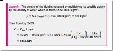
In the special case of all fluids having the same density, this relation reduces to Eq. 2–29, as expected.
Manometers are particularly well-suited to measure pressure drops across a horizontal flow section between two specified points due to the presence of a device such as a valve or heat exchanger or any resistance to flow. This is done by connecting the two legs of the manometer to these two points, as shown in Fig. 2–49. The working fluid can be either a gas or a liquid whose density is r1. The density of the manometer fluid is r2, and the differential fluid height is h.
A relation for the pressure difference P1 – P2 can be obtained by starting at point 1 with P1 and moving along the tube by adding or subtracting the rgh terms until we reach point 2, and setting the result equal to P2:
Note that the distance a has no effect on the result, but must be included in the analysis. Also, when the fluid flowing in the pipe is a gas, then r1 � r2 and the relation in Eq. 2–31 simplifies to P1 – P2 = r2gh.
Other Pressure Measurement Devices
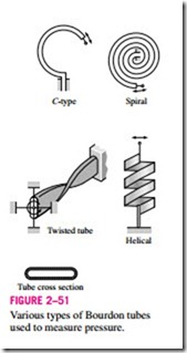
Another type of commonly used mechanical pressure measurement device is the Bourdon tube, named after the French inventor Eugene Bourdon, which consists of a hollow metal tube bent like a hook whose end is closed and connected to a dial indicator needle (Fig. 2–51). When the tube is open to the atmosphere, the tube is undeflected, and the needle on the dial at this state is calibrated to read zero (gage pressure). When the fluid inside the tube is pressurized, the tube stretches and moves the needle in proportion to the pressure applied.
Electronics have made their way into every aspect of life, including pressure measurement devices. Modern pressure sensors, called pressure transducers, are made of semiconductor materials such as silicon and convert the pressure effect to an electrical effect such as a change in voltage, resistance, or capacitance. Pressure transducers are smaller and faster, and they are more sensitive, reliable, and precise than their mechanical counterparts. They can measure pressures from less than a millionth of 1 atm to several thousands of atm.
A wide variety of pressure transducers are available to measure gage, ab- solute, and differential pressures in a wide range of applications. Gage pres- sure transducers use the atmospheric pressure as a reference by venting the back side of the pressure-sensing diaphragm to the atmosphere, and they give a zero signal output at atmospheric pressure regardless of altitude. The absolute pressure transducers are calibrated to have a zero signal output at full vacuum. Differential pressure transducers measure the pressure differ- ence between two locations directly instead of using two pressure transducers and taking their difference.
The emergence of an electric potential in a crystalline substance when sub- jected to mechanical pressure is called the piezoelectric (or press-electric) ef- fect. This phenomenon, first discovered by brothers Pierre and Jacques Curie in 1880, forms the basis for the widely used strain-gage pressure transducers. The sensors of such transducers are made of thin metal wires or foil whose electrical resistance changes when strained under the influence of fluid pressure. The change in the resistance is determined by supplying electric current to the sensor and measuring the corresponding change in voltage drop that is proportional to the applied pressure.
