Systems may be considered to be closed or open, depending on whether a fixed mass or a fixed volume in space is chosen for study. A closed system (also known as a control mass) consists of a fixed amount of mass, and no mass can cross its boundary. That is, no mass can enter or leave a closed sys- tem, as shown in Fig. 2–2. But energy, in the form of heat or work, can cross the boundary; and the volume of a closed system does not have to be fixed. If, as a special case, even energy is not allowed to cross the boundary, that sys- tem is called an isolated system.
Consider the piston-cylinder device shown in Fig. 2–3. Let us say that we would like to find out what happens to the enclosed gas when it is heated. Since we are focusing our attention on the gas, it is our system. The inner sur- faces of the piston and the cylinder form the boundary, and since no mass is crossing this boundary, it is a closed system. Notice that energy may cross the boundary, and part of the boundary (the inner surface of the piston, in this case) may move. Everything outside the gas, including the piston and the cylinder, is the surroundings.
An open system, or a control volume, as it is often called, is a properly selected region in space. It usually encloses a device that involves mass flow such as a compressor, turbine, or nozzle. Flow through these devices is best studied by selecting the region within the device as the control volume. Both mass and energy can cross the boundary of a control volume. This is illus- trated in Fig. 2–4.
A large number of engineering problems involve mass flow in and out of a system and, therefore, are modeled as control volumes. A water heater, a car radiator, a turbine, and a compressor all involve mass flow and should be analyzed as control volumes (open systems) instead of as control masses (closed systems). In general, any arbitrary region in space can be selected as a control volume. There are no concrete rules for the selection of control volumes, but the proper choice certainly makes the analysis much easier. If we were to analyze the flow of air through a nozzle, for example, a good choice for the control volume would be the region within the nozzle.
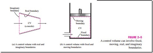
The boundaries of a control volume are called a control surface, and they can be real or imaginary. In the case of a nozzle, the inner surface of the nozzle forms the real part of the boundary, and the entrance and exit areas form the imaginary part, since there are no physical surfaces there (Fig. 2–5a).
A control volume can be fixed in size and shape, as in the case of a nozzle, or it may involve a moving boundary, as shown in Fig. 2–5b. Most control volumes, however, have fixed boundaries and thus do not involve any moving boundaries. A control volume can also involve heat and work interactions just as a closed system, in addition to mass interaction.
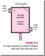
As an example of an open system, consider the water heater shown in Fig. 2–6. Let us say that we would like to determine how much heat we must transfer to the water in the tank in order to supply a steady stream of hot water. Since hot water will leave the tank and be replaced by cold water, it is not convenient to choose a fixed mass as our system for the analysis. In- stead, we can concentrate our attention on the volume formed by the interior surfaces of the tank and consider the hot and cold water streams as mass leaving and entering the control volume. The interior surfaces of the tank form the control surface for this case, and mass is crossing the control surface at two locations.
In an engineering analysis, the system under study must be defined care- fully. In most cases, the system investigated is quite simple and obvious, and defining the system may seem like a tedious and unnecessary task. In other cases, however, the system under study may be rather involved, and a proper choice of the system may greatly simplify the analysis.


