ACCUMULATOR SAFETY CIRCUITS
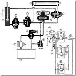
The circuit in Figure 9-11 is used to automatically bleed off a charged accumulator when the pump is shut down to prevent accidental operation of an actuator or to make it safe to open the system for service. The bleed-off is accomplished through a spring offset directional control valve and a fixed restriction. The directional valve solenoid is actuated by the prime mover switch, so that the solenoid energizes whenever the pump is started (see view A). This blocks the bleed passage during normal operation.
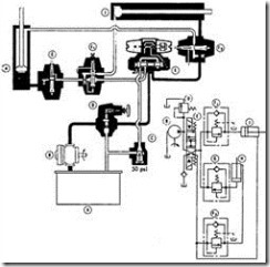
When the pump is shut down (view B), the spool spring shifts the directional control valve and opens the accumulator to tank through the restriction. The manual valve shown is used to control accumulator discharge rate to the system. The auxiliary relief is set slightly higher than the system relief valve and limits pressure rise from heat expansion of the gas charge. The accumulator must have a separator, such as a diaphragm, bladder, or piston, to prevent loss of gas preload each time the machine is shut down.
RECIPROCATING CIRCUITS
Conventional reciprocating circuits use a four-way directional control valve piped directly to a cylinder or hydraulic motor to provide reversal. When a differential cylin der is used, retracting speed is faster than extending speed because of rod volume.
Regenerative Advance
The principle of the regenerative circuit is shown in Figure 9-12. Note that the “B” port on the directional control valve, which would conventionally connect to the cyl-
inder, is plugged and the rod end of the cylinder is connected directly to the pressure line. With the valve shifted to connect the pressure or “P” port to the cylinder’s cap end (view A), flow out of the rod end joins pump delivery to increase the cylinder speed. In the reverse condition (view B), flow from the pump is directly to the rod end of the cylinder. Exhaust flow from the cap end returns to the tank through the direc tional control valve.
If the ratio of cap end area to rod end annular area in the cylinder is 2:1, the cylinder will advance and retract at the same speed. However, the pressure during advance will be double the pressure required for a conventional circuit. This is because the same
pressure in the rod end, effective over half the cap end area, opposes the cylinder’s advance. With a higher ratio of areas, extending speed will increase proportionally.
Regenerative Advance with Conventional Pressure Advance
The regenerative principle also can be used to increase advance speed with a changeover to conventional advance to double the final force. In this circuit (Figure 9- 13), a normally closed pressure control valve in effect plugs the “B” port of the directional valve during regenerative advance. When the pressure setting of the pressure
control valve is reached, it opens to route oil from the rod end to tank through the directional control valve.
The 5-psi check valve permits oil from the rod end of the cylinder to join pump deliv ery during regenerative advance, but prevents pump delivery from taking this route to tank during conventional advance. When the directional control valve shifts to retract the cylinder, pump output is through the check valve in the pressure control valve to the rod end of the cylinder.
CLAMPING AND SEQUENCE CIRCUITS
In many applications, such as clamping a work piece and then machining it, it is nec essary to have operations occur in a definite order, and to hold pressure at the first operation while the second occurs. Following are two of several such circuits.
Sequencing Circuit
Figure 9-14 shows a method of having machine motions occur in a definite sequence, using one directional control valve and two sequence valves. The counterbalance valve shown is used to control the descent of the vertical cylinder. The sequence is as follows.
Cylinder H extends. Solenoid E-a is energized. This causes the delivery of the hydraulic pump (B) to flow through valves D, E, Fl, and the integral check valve of G into the head end of cylinder H. Discharge from the rod end of cylinder H flows freely to the tank through the integral check valve of F2 and valves E and C.
Figure 9-14 Sequencing circuit.
Cylinder J extends, holding pressure on cylinder H. Solenoid E-a remains energized. Pressure increase, on completion of step 1, causes flow to sequence through Fl into the head end of cylinder J. Discharge from the rod end of cylinder J flows freely to tank through valves F2, E, and C. Valve Fl ensures minimum pressure equal to its setting in cylinder H dur ing the extension stroke of cylinder J. When cylinder J is fully extended, pressure increases to the setting of relief valve D, which provides overload protection for the hydraulic pump B.
Cylinder J retracts. Solenoid E-b is energized. Delivery of the hydraulic pump B is directed through valves D, E, and F2 into the rod end of cylin-
Figure 9-14 Continued.
der J. Discharge from cap end of cylinder J flows freely through the inte gral check valve of Fl and valves E and C to the tank.
Cylinder H retracts. Solenoid E-b remains energized. When cylinder J is fully retracted, pressure increases and causes flow to sequence through F2 into the rod end of cylinder H. Discharge from the head end of cylinder H flows through valve G at its pressure setting and then freely to tank through valves F, E, and C. Valve F2 ensures minimum pressure equal to its setting in the rod end of cylinder J during the retraction of cylinder H. Valve G provides back pressure to prevent cylinder H from falling out of control while lowering.


