Circuit analysis
In this chapter, some basic circuits incorporating standard valves and actuators are presented. Every application is different so it is not possible to cover all the possible arrangements, but with the use of these basic simple elements, many more complex circuits can be developed.
It should not be thought that circuit design is always as straightforward as may seem from these circuits. Circuit design is very much an art, to be learnt through experience. One very good way of learning the fundamentals of design is to attend one of the many customer training courses given by most of the major pneumatic companies.
When developing complex circuits, difficulties may be caused by a failure to appreciate that certain circuit states may occur with unexpected results. A common fault is to keep on adding circuit elements to cover problems as they arise, with each addition bringing in its own difficulties. In such an instance, it is always better thoroughly to analyse the cause of the problem which may often be solved by simplification rather than by adding complexity. Pneumatic valves are readily obtainable and are comparatively cheap to buy, so one often sees unnecessarily complex circuits, which quite obviously have been developed by a process of continuous additions. It is worthwhile spending some time with even the simplest circuit to make sure that it cannot be improved.
In the circuits described here, the symbols used are the CETOP symbols, according to BS 2917. These are listed extensively in the Data Section. The convention used is that the valves and cylinders are shown in their un-operated or rest position. All the valves used are standard types, available from a number of suppliers. It is conventional to indicate the power connections by solid lines and the pilot connection by dotted lines, but it is not always easy to define which is which, and in some layouts, the distinction is not kept.
Single-acting cylinder operation
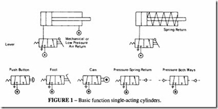
These cylinders are power operated in one direction only, the return stroke being achieved either by a spring, which may be internal to the cylinder, or more usually by an external spring or weight. Figure 1 shows such a cylinder, operated by a three way valve. By utilising the difference in area between the two sides of the piston, it is also possible to use a double acting cylinder operated by a three-way valve, with a constant supply to the return
side as shown. Valves may be operated by a variety of mechanical means, by air pressure acting on the spool ends, by electric solenoids or by a combination of these.
Double-acting cylinder operation
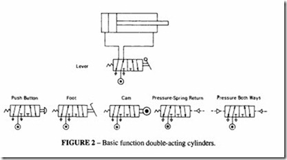
Double-acting cylinders are power operated in both directions and require a four-way valve as shown in Figure 2. The purpose ofthe four-way valve is to insure that, as one side of the piston is pressurised, the other can be vented. Note that afour-way valve is so called because there are four paths or ways through the valve. Such a valve usually has five ports -one inlet, two outlets to the cylinder and two exhaust ports. For pilot operated valves there will also be one or two pilot ports. The valve shown in the figure is a four-way, five port, two-position valve. Five-port valves can also be used when different pressures are required for extension and retraction.
Remote control by pilot operation
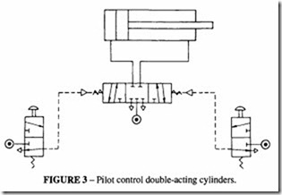
It is often convenient to operate a cylinder from a remote position, as in Figure 3. The main valve, which is sized to take the full flow, is mounted close to the cylinder and is actuated by pilot signals from a pair of three-way valves. The main valve in this example is a three position, four-way valve. A pilot signal shifts the main valve from the neutral or central position; removal of the pilot signal allows a spring to return the valve to neutral. In the central position, the valve traps the air on both sides of the piston; another form of three way valve has a central position in which the air is vented from the cylinder. The former type is more economical in air consumption, the latter allows free movement of the piston in the central position
Speed control of cylinders
Usually it is desirable to control the speed of movement of a cylinder, at least in one direction. The most convenient way of doing this is to restrict the air flow in the exhaust FIGURE 4- Speed control double-acting cylinders.
side of the cylinder. This creates a back pressure on that side which slows down the piston movement. This is a much better way of speed control than restricting the inlet side which leads to instability.
In Figure4 a typical circuit is given for the case where it is required to restrict the speed in both directions. Between the cylinder and main valve is a pair of restrictor valves. These valves control the flow rate in one direction through an adjustable, screw down restrictor; flow in the other direction is unrestricted through a non-return valve. A warning should be given about the use of restrictions in the exhaust: if there is an external force on the piston or if a high kinetic energy is generated, there may be excessive pressures produced in the exhaust circuit. This may require the incorporation of a pressure relief valve set at a safe pressure.
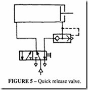
The other extreme of speed control is when maximum operating speed of actuation is desired, as for example when the piston is used for impact. In this case a quick exhaust valve, which allows unrestricted flow from one side of the piston to atmosphere, is used, as in Figure 5. This valve is symbolised as a pilot operated shuttle; typically it incorporates a resilient disc which moves from one seat to the other; on the exhaust side the passages are generously sized. To be effective, it must be mounted very close to the cylinder port which is to be exhausted. In the diagram, the valve forms part of the supply circuit when the cylinder is retracting, but it exhausts directly when pressurised from the cylinder.
Automatic cylinder return
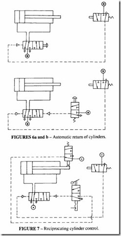
A common requirement is for a single-stroke actuation upon operation of the main valve, followed by automatic return. This is achieved by incorporating a cam-operated pilot valve which sends a signal to the main valve reversing its position. In Figure 6a, the cycle is initiated by depressing the hand-operated pilot. A momentary supply of air is sufficient to move the main valve into the position where it causes the cylinder to extend; when the piston rod triggers the cam valve, it sends a signal to the main valve to return it to its former position, and the cylinder then retracts.
It is possible to actuate the cycle with a pilot valve which is hand-operated and pressure returned, as in Figure 6b. Whilst this is functionally satisfactory, it is not good practice to allow pressure to move a valve handle, with the possibility of injury by trapping the hand of the operator.
Automatic cylinder cycling
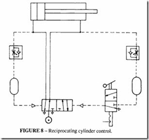
Figure 7 demonstrates how it is possible to achieve continuous reciprocation of the cylinder so long as the hand-operated valve remains in the selected position. Two cam operated pilot valves define the extent of the piston travel which need not, indeed in most cases should not, be at the mechanical ends of the cylinder. The hand-operated pilot valve has a detent which allows the valve to be left continuously in either the actuated or the rest position. In this example, the cylinder always stops in the retracted position, but it could equally well be arranged to stop in the extended position.
It is important to design an automatic circuit so that it always stops with the components in the correct position for restarting. It would not, for example, be correct to initiate reciprocation by turning on an air supply to the main valve, because the cylinder might stop in mid-stroke when the supply was cut off and there would be uncontrolled movements when the supply was restored. Furthermore there would be no locked-in pressure and therefore no holding force in the stopped position.
Reciprocation without position valves
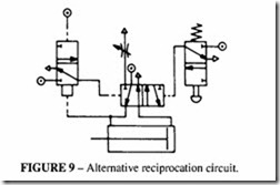
It is not always possible or convenient to arrange for the reciprocation to be triggered by mechanically operated pilot valves; an alternative way of initiating cylinder reversal is by sensing the cylinder pressures. A circuit which demonstrates the principle is shown in Figure 8. In this arrangement, the main supply between valve and cylinder is also passed via a restrictor valve to the pilot port of the main valve. Two reservoirs are incorporated in the pilot lines and the stroke length is governed by the build-up of pressure in the reservoirs, which are charged by restrictor valves. For fast cycling, the reservoirs may be unnecessary.
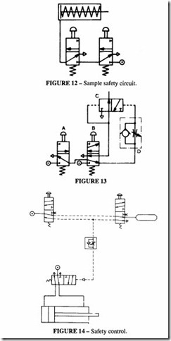
Another circuit is in Figure 9, which uses a differential-area, pressure-operated pilot valve. This valve switches with a lower pressure on one pilot; the lower pressure side is usually diaphragm actuated, commonly requiring only about 0.2 bar for operation. When the cycle is started by operation of the hand-operated pilot, the cylinder extends. Because
the flow from the return volume is restricted by the restrictor valve, pressure builds up in that line and triggers the pilot.
The positional accuracy of the systems which rely on pressure is not as good as those with mechanically operated valves. If it is not easy to mount these valves, the designer should consider the use of cylinders with integral control valves or one of the piston sensing devices described in the chapter on Construction of Pneumatic Cylinders.
Controlling the speed of operation
The frequency of reciprocation can be controlled by incorporating restrictor valves in the exhaust lines as described above, but this may not always be adequate. In some applications it is desirable to arrange for a time delay at one end or both ends of the travel. A purely pneumatic time delay can be arranged by the use of a reservoir, which is merely a chamber which can be charged up by a controlled air supply from a restrictor valve. One such circuit is illustrated in Figure I 0. Towards the end of the piston stroke a cam-operated pilot valve is actuated; but before the main valve is switched, the air from this pilot has to pass through the variable restrictor and charge up the reservoir. It is only when the pressure in the reservoir reaches the pressure required to operate the main valve that it switches, allowing the piston to return. This circuit is suitable for fairly small time delays (in practice up to about 10 s). Longer delays require the use of very fine bleed holes or large reservoirs.
A reservoir is usually made from the same section tubing as a standard cylinder, with a port in the end instead of a piston. For adjusting the time delay, it is possible to use a variable volume reservoir, but these are not readily available and a much cheaper way of
achieving the same end is by the use of a variable restrictor.
The circuit of Figure I 0 can be considered to be the “classical” method of obtaining a time delay, but there are now available special time-delay valves which are able to effect the same result withjusttheone device. The main advantage of these valves is thatthe time delay can be set by a graduated control knob; they do not rely on trial and error. Valves with time delay settings between 0.2 seconds and I 00 minutes are available. These valves can be looked at as three-way pilot valves with a time delay on the pilot circuit and are available in normally closed or normally open types.
These techniques of controlling actuation times can equally well be replaced by electrical methods.
Dual control of a cylinder
It may be necessary to control a cylinder from more than one position. Two ways of doing this are shown in Figure 11.The in actuation uses a pair of valves connected by a shuttle, the out actuation uses a number of pilot valves in series.
Safety circuits
It is sometimes necessary to ensure that both an operator’s hands or his feet are occupied during a cycle, for example in the operation of a press or while a cutter is rotating. One way of doing this is by the circuit of Figure 12, which has two palm-operated valves in series. While this has the merit of simplicity, it is not to be recommended for two reasons: the operator can by-pass the safety system by tying down one of the valves ora valve may stick in a dangerous position. Such a circuit may not meet the safety code that applies to the use ofthe machine being operated. There are safer circuits that are less susceptible to operator misuse; they require not only the operation of both valves but also that they be actuated simultaneously.
One example is shown in Figure 13. If only valve A is operated, the air supply from A passes through Band D, which causes C to switch and vent the supply line; if only B is operated, the air supply from B passes through D and also switches C. It is only when A and B are operated simultaneously that the left pilot line of Cis press uri sed, allowing air
to pass to the cylinder. The air to the right hand pilot is delayed by the restrictor valve, so the left hand pilot signal dominates.
An alternative safety circuit is shown in Figure 14. In the un-operated position, air is supplied through both valves to a reservoir. Depression of only one valve discharges the reservoir to atmosphere. Simultaneous depression of the valves causes the selector to admit air to the cylinder. A small time interval between the depression of the valves is permissible, which can be adjusted by trial. In both Figures 13 and 14, release of either valve vents the signal to atmosphere.
When installing a safety interlock it may be more convenient to use a two-handed control unit, which performs the same function as one of the above circuits. These units are available from a number of suppliers. Two kinds are available: the simplest is a valve which gives an output when it receives two input signals within 0.5 s; the other kind combines the hand-operated valves and the control unit in the same block. These proprietary valves are usually designed to meet local safety legislation and must be installed in accordance with an approved Code of Practice (eg as issued by the Health and Safety Executive in U.K. and OHSA in U.S.A.).
Control of multi-position cylinders
Sometimes multi-position cylinders are used to provide operation with varying stroke lengths. This type of cylinder is not often used today, because it is easier to obtain the same effect using cylinders with integral control valves, but for completeness two typical circuits are included here in Figures 15 and 16.
Complex circuits
It will be apparent that pneumatic circuits can be highly complex, involving pneumatic or electric logic controls. Further analyses can be found in other chapters. Usually the power section of the circuit is fairly straightforward, with the logic section requiring the greatest attention.
Pneumatic logic circuits
Exactly the same logic functions that are found in a micro-processor can be replicated pneumatically, and in general it is possible, having defined the logic circuit necessary, to perform a particular sequence of events, to realise that circuit either electronically or pneumatically. A complete range of valves are available to do the latter.
The choice of which option to follow will depend on the circumstances. As a general rule, the more complex the circuit, the more likely it is that an electronic solution via a Programmable Logic Controller (PLC) will be better. It may also be the case that a combination of the two will give the best results.
Moving part logic elements
Logic functions can be performed by simple valves or combination of valves. Interest in pneumatic logic was originally stimulated by the development of pure fluidic devices such as turbulence amplifiers and Coanda effect valves. In theory, because these have no moving parts, they should be capable of extreme miniaturisation. Systems built with such valves have been shown to work, but unreliably. They required very high air quality and very low operating pressures (much less than I bar). The pressure amplification between logic and power stages always proved to be a weak part of the system. The have all but disappeared apart from academic interest as a research tool.
Their place has been taken by moving part logic (MPL) valves, which work on normal system pressure and are really miniature forms of conventional valves. Practically all logic circuits use these valves. The air quality has to be good (but not exceptionally so), and is preferably non-lubricated and dry.
A number of manufacturers make these valves and each offers its own system of interconnection, which can either use sub-base mounting or push-in tubes connectors, using 4 mm or 5 mm tubing; these reflect the two forms in which power valves are available. There is no widely acceptable standard for these elements, so it is best to keep to the products of one manufacturer.
The development of a logic circuit based on MPL elements requires familiarity with one of the basic techniques that are available: Boolean algebra, Karnaugh-Veitch maps, Cascade techniques, Grafcet function charts and others. These methods, familiar to the designer of PLCs, are not usually part of the tool-box of the pneumatic designer, however most companies who manufacture MPL also run training courses in which it is possible to learn the techniques of using their own products.
Basic logic functions
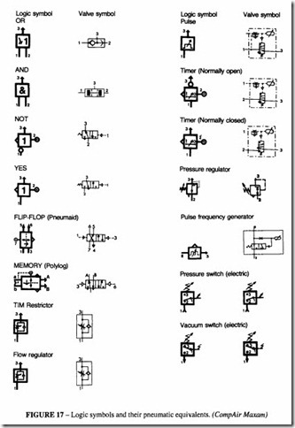
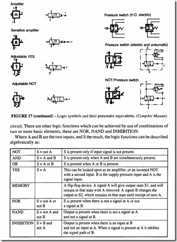
The basic logic functions are NOT, AND and OR, but for logic control functions one needs to add YES, which is a modified form of NOT, and MEMORY. Figure 17 shows the various MPLs that are available, the ISO logic symbols, their pneumatic equivalents and a number of other miniature components which may be required for a complete pneumatic
Most manufacturers can supply MPLs of the first five kinds. The others may be available either as valves in their own right or as a combination of two or more of the others. For example NOR is realised by an OR with its output connected to a NOT, and NAND by an AND with its output connected to a NOT.
Figure 18 shows how the various MPLs can be realised by simple poppet valves.
The logic circuit has to interface with sensing units at the input stage and the power system at the output stage. The sensing units may themselves be pneumatic or electronic, so it is necessary to have available a range of interface devices which can be assembled onto the same sub-base system.
Parts of the circuit may be required to operate at pressures different from that of the line. To accommodate that feature there is an adjustable YES and an adjustable NOT as well as adjustable timers and pressure regulators.
A sensitive amp!ifier is necessary if one wishes to take a signal from a proximity sensor, for example, which may work on a pressure measured in millibars and convert it into line pressure in bars.
Other devices include pulse generators, pulse frequency generators, various pressure switches, all of which have their place in a complete control circuit.
Usually the logic devices have a visual indicator on them to show their state, which is useful when developing the system or trouble-shooting.
