Construction of pneumatic cylinders
Pneumatic cylinders can be classified in various ways such as single-acting, double acting, through-rod, tandem and duplex, cushioned, rotating and miniature. A wide choice of mountings is available: foot mounting, pin end, neck and flange mounting, hinge brackets, spherical rod ends, clevises etc. Pneumatic cylinders of these types are manufactured on similar lines to hydraulic cylinders, except for a difference in the materials of construction and the relative rod sizes due to the lower working pressures of compressed air. A wide range is available commercially to meet the needs of most users and are readily made from standard sections, end caps and pistons.
If possible one should adopt a standard design to allow for interchangeability.
The following standards should be referred to for consistent dimensions of cylinders.
• BS ISO 6431 for 32 mm to 320 mm bore (32, 40, 50, 63, 80, 100, 125,160, 200, 250 and 320 mm)
• BS ISO 6432 for 8 mm to 25 mm bore (8, 10, 12, 16, 20, 25 mm)
• BS 5755 (ISO 4393) for recommended stroke lengths
• BS 6331 (ISO 6099) for mounting styles
• BS 5755 (ISO 4395) for piston rod threads
• ISO 6430 for mountings integrated in the main body of the cylinder.
Cylinders made to these standards are usually listed by manufacturers as ISO cylinders. The former British standard BS 4862 has now been withdrawn.
Other standards such as VDMA 24562, DIN 24335, CNOMO/AFNOR NFE are also to be found.
When considering interchangeability, the level of standardisation has to be considered.
When replacing ISO cylinders, it is not always possible to changejust the cylinder: it may be necessary to change both cylinder and mountings. With VDMA and CNOMO/ AFNOR, the bare cylinder is interchangeable.
Imperial (inch sizes) are still manufactured, mainly in the U.S.A. but to no particular standard dimensions.
Various cylinder designs are illustrated in Figures I to 5.
Tube materials
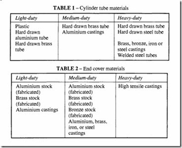
Material selection must ensure adequate resistance to wear, corrosion and accidental damage. Particular attention must be given to the choice of materials in special environ ments such as explosive atmospheres where aluminium alloys are not permitted or where corrosive atmospheres are present. Refer to Tables 1 to 5 for a summary of available materials. Plastics were introduced for light weight applications but have now practically disappeared, although for special applications glass- or carbon-fibre reinforced resin is used.
Cylinders can be made in magnetic or non-magnetic versions.
Cylinder tubes are cheaply made from drawn metallic tubing. For light duty, aluminium is commonly used; for medium duty, although less commonly, brass tubing is used. For the most robust applications, both stainless and alloy steel tubing is used.
If non-stainless steel is used, attention must be given preventing corrosion. Large size cylinders may be cast in aluminium or steel. Welded steel tubes are also used.
To ensure low friction and to minimise seal wear, a fine finish in the bore is essential to 600 ).lm or less when elastomeric seals are employed. This may require honing even with hard drawn seamless tubes. Hard chrome plating, honed and polished is used on alloy cylinders, and hard anodising on aluminium tubes.
End covers
These may be cast or fabricated from stock, normally in the same material as the tube to avoid the possibility of electrolytic corrosion. This is an important consideration, particularly since the air may be saturated with moisture.
The method of attachment of the end covers varies. Covers may be threaded, welded or mechanically secured. A common construction for medium and heavy duty cylinders is
the use of tie rods (usually four) made of high tensile steel. Square section tubes allow for attachment of the end caps by screws threaded into the body of the section.
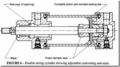
The end covers incorporate the inlet and outlet ports and the cushion chambers where fitted. Pneumatic cushioning is required in order to absorb the dynamic forces at each end of the stroke. The cushioning can be fixed or adjustable by means of a needle valve, as in Figure 6. Where the additional feature of pneumatic cushioning is not required, a simple elastomeric washer built into the end cap may suffice.
One or both of the end covers carry the rod bearings and rod seals according to whether the design is of single rod or through-rod designs. A through-rod cylinder is symmetrical in end cap design.
Tie rod cylinders
The main requirement of a tie rod construction is that the end covers cannot move when the cylinder is under pressure. This implies tensioning the rods to a load equivalent to the maximum pressure in the cylinder. For long cylinders there may bea central tie rod support ring. Any stripping down of the cylinder must be followed by the correct tightening of the tie rods to the manufacturer’s specification.
Pistons and piston rods
Pistons are usually aluminium alloy stock, castings or forgings. Other materials are steel, brass or bronze.
They may be of one-piece or multi-piece construction. Cup seals require multi-piece construction. 0-ring or square section seals can be fitted into a one-piece construction.
An additional nylon wear ring (or two rings) may be fitted to provide support for the assembly. One of the design problems of a long cylinder is its stability under compression, so the providing of this extra support to the piston is worth incorporating. This is less a problem with through cylinders where the opposite rod gives the extra stability in compression.
For operation at high temperature, beyond the range of elastomeric seals, automobile type piston rings may be used as piston seals. The leakage past such seals is much greater than with pressure-energised elastomer seals and the wear rate is higher.
The usual choice for piston rods is a medium carbon steel ground and polished or chromium plated or ground and polished stainless steel. Hardened steel rods may be employed although hard chrome plating is usually sufficient. High finish is necessary to minimise wear of the rod seals.
The piston rod diameter is chosen with respect to end loading and length- the latter governing whether the rod behaves as a rigid rod or as a column subject to buckling. The rod diameter should be chosen so that buckling length is well outside the rod length, treating the rod as pin-ended at both ends.
Heavy duty cylinders may have larger rod diameters than normal but there may be manufacturing restrictions if standard cylinder sizes are used.
Long stroke cylinders may present a special problem because of the length of rod involved. Besides the possibility of buckling under compression, the weight of a long rod will tend to make it sag when mounted horizontally. Furthermore, long rods tend to vibrate in a frequency range that may be excited by the operating conditions.
A solution which may cure these problems is to increase the length of the rod bearing, so that the longer the stroke, the longer becomes the rod bearing.
Piston rod bearings are usually of sintered bronze but may also be of plastic material inserted in the form of a sleeve in the end cover.
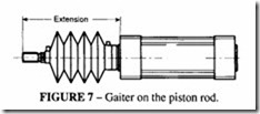
Simple elastomer seals or fabricated rings are satisfactory for the rods of light duty cylinders. Medium or heavy duty cylinders have multiple seals or seal sets. A second or wiper seal is usually mounted on the outer end of the bearing to prevent dirt being drawn into the main seal as the rod retracts. Although this is standard practice, these seals are not really adequate for dirty or wet conditions and so in these circumstances, consideration should be given to full protection by enclosing the rod with a sleeve or gaiter (Figure 7). Such gaiters are a type of bellows to permit the full extension and retraction of the rod, the number of corrugations depending on the total length. The design must allow for “breathing” so that they cannot collapse under the action of internal pumping.
Non-lube cylinders
For use with a non-lubricated air supply, in applications such as the food industry and drug manufacture, cylinders are made from materials that do not require additional lubrication. Most modern cylinders are supplied in this form as standard so that they can be used with or without lubrication. The cylinders may have an internal finish of electro-less nickel and PTFE, giving a very hard surface with good wear and self lubrication properties. Other
finishes involve anodised aluminium and sprayed on coatings. The life of such a cylinder is very little less than when lubricated. There is no harm done if the non-lube cylinder is used with lubricated air, but once having used lubrication most manufacturers advise that it has to be continued.
Cylinder mounts
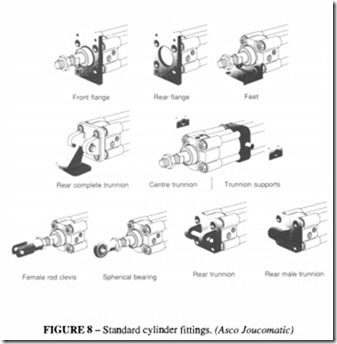
A wide variety of mounts are available for air cylinders and the choice of the most appropriate type must be chosen on the basis of the force to be reacted. Mounts can be broadly categorised as floating and non-floating. A floating mount anchors the cylinder at one point only, with freedom to move in one plane. This is the preferred type because it allows the cylinder to compensate automatically for any misalignment without introduc ing side or bending loads on the rod. For a fully floating mounting, ball and socket or universal joint type mounts can be used and fitted to the rear end cover. These are satisfactory provided the cylinders are short. The main types of mount are shown diagrammatically in Figure 8.
Fully floating mounts are less satisfactory with long stroke cylinders. A type of mounting which can be used in such cases is a mid-position flexible mount, with trunnion pins locating in a ball joint bearing.
Any such mounts must provide for the transmissions of the direct load produced by the
pressure in the cylinder without any twisting or bending loads caused by the method of mounting. End fixings are preferred to central trunnion mounting.
Rigid mountings are used where the cylinder has to have good support. They may be single or double, the latter being suitable for long stroke cylinders. Foot and centre-line mounts are normally incorporated in the construction of the cylinder end covers. Single foot mounts are only used in light duty applications. Pedestal and flange mounts are attached to the end covers and supplied by the manufacturer.
Rigid mounts can absorb the end thrust on the cylinder centre-line or in a plane parallel to it but removed from the centre-line. The former is to be preferred where the forces are heavy, otherwise bending is induced in the mount. The mounting bolts are then only stressed in tension, provided that there is no misalignment.
Examples of mounts which absorb the forces on the cylinder centreline are centre-line lugs, mounting by extension of the side rods, flange mounting and screwed nose mounting. These mounts may tolerate some misalignment when the piston rod is extended but little or none when contracted.
End-mounted cylinders may require extra support at the freeendofthecylinder. Double mounts are chosen when a long stroke is overhung. Long cylinders may have an additional extra support.
Foot mounts which do not absorb forces on the centre-line are unsatisfactory where the forces are heavy or where shock loads are involved. The mounting bolts are subject to compound stresses which may be indeterminate, the cylinder itself is subject to bending or buckling and the platform on which the mounts are attached may distort. A bent cylinder may require a greater air pressure to operate or the friction induced may be such as to prevent operation altogether.
Rod ends
These are finished in a variety of ways, some of which are shown in Figure 8. These are standard forms supplied by the manufacturer. A clevis or tongue end or a universal joint is to be preferred where there is any chance of misalignment. Bending forces on the piston rod are to be avoided at all cost.
Non-rotating rod cylinders
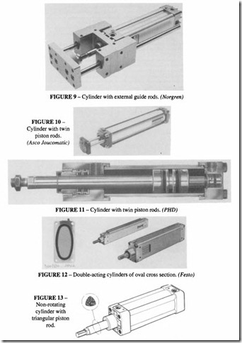
In the majority of applications for cylinders it is permissible to allow the rod and piston to rotate freely, any angular orientation being taken care of by the mechanism to which the cylinder is attached. Where this is not possible, a non-rotating cylinder can be employed. Such a cylinder maintains the angular orientation of the rod and its end fitting without any further guide mechanism. A variety of ways are available to achieve this, Figures 9 to 14:
• external guides,
• twin piston rods,
• guide splines in the piston,
• oval pistons,
• non-circular (oval, square or triangular) section piston rods,
• linear ball supporting splines in the piston rod.
External guides are the most usual because they can be designed to take substantial torque and bending loads, Figure 9. Guide units can be attached to the end caps of standard cylinders, which is an advantage in standardisation. In addition to the non-rotating function they are also used where there is an overhung load on the piston roads which requires extra support.
Mechanisms which are built into thecylinderitself can tolerate only a limited torque and no extra bending load. The one exception to this is the twin-rod type which can accept transverse loading in the plane of the axis through the rods. Suppliers of special cylinders can supply design curves giving the maximum permissible transverse loading and torque at the various stroke lengths.
Compact (short stroke) cylinders
Where space is limited and the required stroke is short, special compact cylinders, Figure
15, can be used; their most common use is for clamping purposes. They can show considerable space savings over the ISO standard cylinder (a reduction in overall length of up to 80%). They can be machined out of solid, with the end caps integral with the body, or using drawn tubing the ends can be retained by circlips. Porting is machined into the body of the cylinder. They can be mounted by through bolts in the body. Non-rotating versions of compact cylinders are also available.
Composite and special cylinders
By combining cylinders together end-to-end it is possible achieve some special effects.
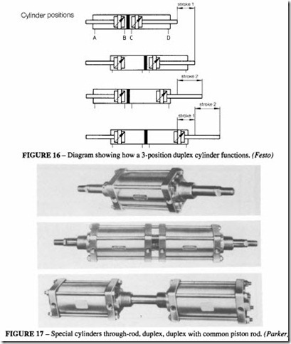
With two cylinders back to back (Figures 16 and 17) a multi-position cylinder is
obtained. Usually the cylinders are of equal diameter. If they are of the same stroke length, a three-position device is produced, if of unequal length a four-position device. A similar effect is achievable with a common piston rod A through rod cylinder with a common piston is completely balanced, giving equal thrust in both directions. This can be used where one end of the rod is inside the machine, leaving the other end to trip a valve.
Position sensors for cylinders
In automation applications, it is often required for a signal to be generated when the cylinder piston reaches a particular position along its stroke, so that the control system can initiate the next phase of the operation. This position may be at either end of the stroke or some point intermediate between the ends. There are several ways in which this can be done (Figure 18):
• The piston rod trips a micro-switch or pneumatic valve.
• Pressure threshold sensors respond to a drop in exhaust pressure when the piston stops moving.
• Magnetic sensors mounted directly on the cylinder barrel sense the magnetic field created by a permanent magnet incorporated in the piston and trigger a reed switch.
Mechanical sensors fitted to the machine
• Hall effect sensors (solid state) triggered by a magnetic piston.
• Pneumatic reed valves, triggered by a magnetic piston.
• Miscellaneous such as photoelectric, inductive and capacitive detectors.
Mechanical trip switches are the traditional method for position sensing and are still widely used and reliable. Pressure threshold sensors respond less to actual position than to piston velocity, so they are only suitable for detecting the end of the piston travel; they may work unreliably with slow moving pistons.
Both of these are gradually being superseded by the two types of magnetic sensors.
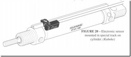
Most manufacturers can supply pistons incorporating permanent magnets, which are suitable for the two main types of magnetic sensor. The cylinder has to be made of a non magnetic material such as stainless steel, brass, aluminium or plastic. In the reed switch, the contacts are made mechanically by the presence of the magnet. Some switches incorporate an LED or warning lamp in the body of the switch as in Figure 19. Hall effect sensors have no moving part, but the presence of a magnetic field causes a current to flow in the switch. Reed switches can equally well carry a.c. or d.c., Hall effect switches only d.c. The main advantage of a Hall effect switch is its long life and so it is more suitable for rapid switching rates; there is also no possibility of switch bounce.
These magnetic switches can be clamped to the outside of the cylinder barrel or fitted into a fastening track (Figure 20). With some types of attachment it is possible to have two switches located at the same point of the cylinder giving the security of redundancy.
mounted in special track on cylinder. (Kuhnke)
Pneumatic reed switches are also available. These are triggered by a magnetic piston in the same way as an electronic switch, but instead of an electric circuit they open a miniature pneumatic valve.
Cylinder with pneumatic clamp
This is an extra cylinder, surrounding the piston rod of the main cylinder, Figure 21, which clamps the rod by spring pressure, ensuring that if air pressure should fail, movement is impossible because the cylinder is locked in position. When pressure is restored the clamp is released.


