Hydraulic fluids
The liquid in a hydraulic system is used to convey energy and produce the required force at the actuators. Very early systems used water (in fact the name hydraulic implies water) but water has many disadvantages, the most obvious of which are its relatively high freezing point of 0 °C, its expansion when freezing, its corrosive (rust formation) properties and poor lubrication. Modern fluids designed specifically for hydraulic circuits have therefore been developed.
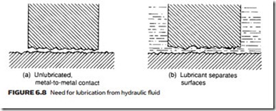
The fluid conveys power in a hydraulic circuit, but it must also have other properties. Chapter 5 described the seals found in actuators. Moving parts in valves do not have seals; instead they rely on fine machining of spools and body to form the seal in conjunction with the fluid. Despite fine machining, irregularities still occur on the surface, shown in exaggerated form in Figure 6.8a. The fluid is required to pass between the two surfaces, holding them apart as in Figure 6.8b, to reduce friction and prevent metal-to-metal contact which causes premature wear. Sealing and lubrication are therefore two important properties of hydraulic fluid.
The temperature of hydraulic fluid tends to rise with the work done, an ideal operating temperature being around 50 °C (a useful quick check is to touch pipes in a system: the hand can be left indefinitely on metal at 40 °C; can touch metal at 50 °C but long contact is distinctly uncomfortable; but cannot be left for more than a second or so on metal at 60 °C. If you cannot touch the pipes, the oil is too hot!). The fluid must be able to convey heat from where it is generated (valves, actuators, frictional losses in pipes) and must not be affected itself by temperature changes.
The fluid can cause deterioration of components. An extreme case is water causing rust, but less obvious reactions occur. A water–glycol fluid, for exam- ple, attacks zinc, magnesium and cadmium – all fairly common materials. Some synthetic fluids interact with nitrile and neoprene, and special paint is needed on the inside of the reservoir with some fluids. The fluid must therefore be chosen to be compatible with the rest of the system.
The fluid itself comes under attack from oxygen in air. Oxidation of fluid (usually based on carbon and hydrogen molecules) leads to deleterious changes in characteristics and the formation of sludge or gum at low-velocity points in the system. The resulting oxidation products are acidic in nature, leading to corrosion. The fluid of course must be chemically stable and not suffer from oxidation. The temperature of fluid strongly influences the rate of oxidation, which rises rapidly with increasing temperature.
The most common hydraulic fluid is petroleum-based oil (similar to car engine oil) with additions to improve lubrication, reduce foaming and inhibit rust. With the correct additives it meets all the requirements and does not react adversely with any common materials.
Its one major disadvantage is flammability; petroleum oils readily ignite. Al- though few (if any) hydraulic systems operate at temperatures that could ignite the oil, a major leak could bring spilt oil into contact with an ignition source. The probability of leakage needs consideration if petroleum oils are to be used.
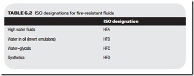
If safety dictates that a fire-resistant fluid is required there are four basic choices (Table 6.2).
The most common form is a water-in-oil emulsion (roughly 40% water, 60% oil). Oil-in-water emulsions are sometimes used, but their lubricating properties are poor. Both types of mixture have a tendency to form rust and to foam, but these characteristics can be overcome by suitable additives. Both types also need regular checking to ensure the correct oil/water ratio is being maintained.
Another non-flammable fluid is a water–glycol mix. This consists of roughly equal proportions of water and glycol (similar to car antifreeze) plus additions to improve viscosity (see below), inhibit foaming and prevent rust to which water- based fluids are vulnerable. Glycol-based fluids interact with many common materials (particularly zinc, cadmium and magnesium), so the system components must be carefully chosen.
High water content fluids (HFA) use around 95% water with 5% additives, making them totally non-flammable. They are often called 95/5 microemulsion. Their use needs some care as they have very low viscosity, for all practical purposes the same as water, making applications using them prone to leaks at joints and seals. Unlike normal fluids small external leaks can be difficult to see as at the normal 40– 50°C operating temperature the fluid evaporates away without leaving any trace.
Spool valves have an inherent leakage and this can be problematical with low-viscosity fluids such as HFA. Cartridge valves, described in Chapter 4, are therefore often used with HFA.
The high water content makes precautions against rust very important. Any 95/5 components removed from service must be protected against exposure to air. Some manufacturers will not honor their warranties when 95/5 fluid has been used.
Regular checks on water-based fluids are essential to maintain the correct oil/water ratio, the presence of the correct amount of additives and the pH level, all of which will be changed by evaporation. As evaporation increases with temperature water-based fluids are normally operated at a lower temperature than petroleum fluids.
Synthetic fluids based on chemicals such as phosphate esters are also non- flammable and can be used at very high temperatures. These tend to have high densities, which limit the height allowed between tank and pump inlet without cavitation occurring, and do not operate well at low temperatures. Systems with synthetic fluids usually require heaters in the tank to preheat fluid to operating temperature. Synthetic fluids are the most expensive form of hydraulic oil.
viscosity
The properties of a liquid are largely determined by its resistance to flow, which is termed its viscosity. In non-scientific terms we talk about treacle having high viscosity, and water having low viscosity. Both extremes bring problems; a low-viscosity fluid flows easily and wastes little energy, but increases losses from leakage. A viscous fluid seals well, but is sluggish and leads to energy and pressure losses around the system. Hydraulic fluid has to hit a happy medium between these extremes, so some way of defining viscosity is required.
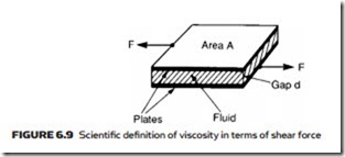
There are basically two techniques of specifying viscosity. Absolute viscosity measures the shear force between two plates separated by a thin fluid film, shown in Figure 6.9. The most common unit is the poise (a cgs unit) which is the measure of shear force in dynes, for surface areas of 1 cm2 separated by 1 cm of fluid. The centipoise (0.01 poise) is a more practical unit.
Kinematic viscosity is the most common, and most practical, way of measuring viscosity. It is measured by recording the time a fixed quantity of oil takes to flow through a capillary tube. It is defined with a unit called the stokes which is the absolute viscosity (in poise) divided by the density (in g cm−3). A practical unit is the centi-stokes; a typical hydraulic fluid will have a viscosity of around 40 centi-stokes and low-viscosity fluid such as HFA about 1 centitoke. Not surprisingly this much lower viscosity means that HFA is very prone to leaks.
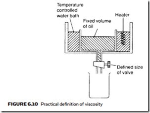
The poise and the stokes are units denoting scientific definitions of viscosity. In hydraulics, all that is really needed is a relative comparison between different liquids. This is achieved with the practical experiment shown in Figure 6.10, where a fixed volume of oil is heated to a test temperature then allowed to drain out through a fixed-sized valve. The time taken to drain in seconds is a measure of the viscosity (being high for high-viscosity liquids and low for low-viscosity liquids).
The test of Figure 6.10 (generally performed at 100 °F and 210 °F with a volume of 60 cm3) gives viscosity in saybolt universal seconds (SUS). The
Fahrenheit basis of these definitions comes from the American origin. Hydraulic fluid normally has a viscosity between 150 and 250 SUS defined at 100 °F, although higher values are used in high-temperature applications.
Viscosity can also be given by similar tests for engine oils devised by the American Society of Automotive Engineers (SAE). These give Winter numbers with suffix W (e.g. 10W, 20W) defined at 0 °F, and Summer numbers defined at 210 °F. An oil rating of 10W SAE, for example, covers the range 6000–12,000 SUS at 0 °F, while 30SAE covers the range 58–70 SUS at 210 °F.
Viscosity decreases with increasing temperature, and this is given in SAE units in the form SAE 10W50, for example. This variation in viscosity with temperature is defined by the viscosity index, a unit based on an arbitrary scale from zero (poor, large variation in viscosity with temperature) to 100 (good, small variation with temperature). The range zero to 100 was chosen to relate to standards obtainable with practical fluids rather than some absolute measurable standard. Most hydraulic oils have a viscosity index of about 90.
The reliability of a hydraulic system is strongly influenced by the state of fluid. Contamination from dirt or the products of oxidation and deterioration of a fluid’s lubrication ability will lead to rapid wear and failure.
Pour point
The pour point temperature is the lowest temperature at which a fluid will flow. In hydraulic systems the pour point temperature should be at least 10°C below the lowest temperature at which the system will operate.


