Pump types
There are essentially three different types of positive displacement pump used in hydraulic systems.
gear pumps
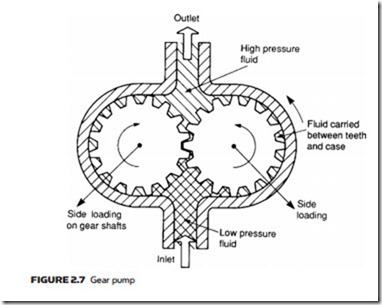
The simplest and most robust positive displacement pump, having just two mov- ing parts, is the gear pump. Its parts are non-reciprocating, move at constant speed and experience a uniform force. Internal construction, shown in Figure 2.7, consists of just two close meshing gear wheels which rotate as shown. The direc- tion of rotation of the gears should be carefully noted; it is the opposite of that intuitively expected by most people.
As the teeth come out of mesh at the center, a partial vacuum is formed which draws fluid into the inlet chamber. Fluid is trapped between the outer teeth and the pump housing, causing a continual transfer of fluid from inlet chamber to outlet chamber where it is discharged to the system.
Pump displacement is determined by: volume of fluid between each pair of teeth; number of teeth; and speed of rotation. Note the pump merely delivers a fixed volume of fluid from inlet port to outlet port for each rotation; outlet port pressure is determined solely by design of the rest of the system. Gear pumps are compact and cheap but are noisy.
Performance of any pump is limited by leakage and the ability of the pump to withstand the pressure differential between inlet and outlet ports. The gear pump obviously requires closely meshing gears, minimum clearance between teeth and housing, and also between the gear face and side plates. Often the side plates of a pump are designed as deliberately replaceable wear plates. The op- erational method of a gear pump means that high displacements can be achieved by multiple parallel gear assemblies driven from a single shaft and motor. Wear in a gear pump is primarily caused by dirt particles in the hydraulic fluid, so cleanliness and filtration are particularly important.
The pressure differential causes large side loads to be applied to the gear shafts at 45° to the center line as shown. Volumetric efficiency of gear pumps at 90% is lowest of the three basic pump types.
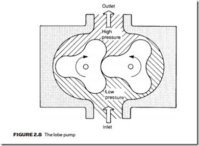
There are some variations of the basic gear pump. In Figure 2.8, gears have been replaced by lobes giving a pump called, not surprisingly, a lobe pump.
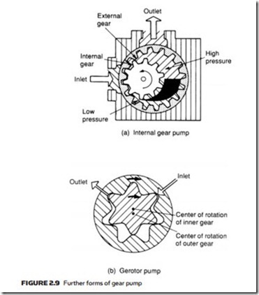
Figure 2.9a is another variation called the internal gear pump, where an external-driven gear wheel is connected to a smaller internal gear, with fluid separation as gears disengage being performed by a crescent-shaped molding. Yet another variation on the theme is the gerotor pump of Figure 2.9b, where the crescent molding is dispensed with by using an internal gear with one less tooth than the outer gear wheel.


