Pump types
There are essentially three different types of positive displacement pump used in hydraulic systems.
Gear pumps
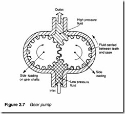
The simplest and most robust positive displacement pump, having just two moving parts, is the gear pump. Its parts are non-reciprocating, move at constant speed and experience a uniform force. Internal construction, shown in Figure 2.7, consists of just two close meshing gear wheels which rotate as shown. The direction of rotation of the gears should be carefully noted; it is the opposite of that intuitively expected by most people.
As the teeth come out of mesh at the centre, a partial vacuum is formed which draws fluid into the inlet chamber. Fluid is trapped between the outer teeth and the pump housing, causing a continual transfer of fluid from inlet chamber to outlet chamber where it is discharged to the system.
Pump displacement is determined by: volume of fluid between each pair of teeth; number of teeth; and speed of rotation. Note the pump merely delivers a fixed volume of fluid from inlet port to outlet port for each rotation; outlet port pressure is determined solely by design of the rest of the system.
Performance of any pump is limited by leakage and the ability of the pump to withstand the pressure differential between inlet and outlet ports. The gear pump obviously requires closely meshing gears, minimum clearance between teeth and housing, and also between the gear face and side plates. Often the side plates of a pump are designed as deliberately replaceable wear plates. Wear in a gear pump is primarily caused by dirt particles in the hydraulic fluid, so cleanliness and filtration are particularly important.
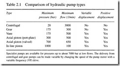
The pressure differential causes large side loads to be applied to the gear shafts at 45° to the centre line as shown. Typically, gear pumps are used at pressures up to about 150 bar and capacities of around 150 gpm (6751 min-1). Volumetric efficiency of gear pumps at 90% is lowest of the three pump types.
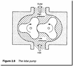
There are some variations of the basic gear pump. In Figure 2.8, gears have been replaced by lobes giving a pump called, not surprisingly, a lobe pump.
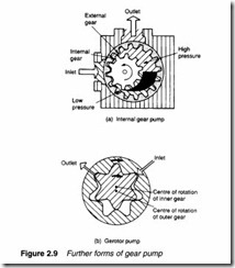
Figure 2.9a is another variation called the internal gear pump, where an external driven gear wheel is connected to a smaller internal gear, with fluid separation as gears disengage being performed by a crescent-shaped moulding. Yet another variation on the theme is the gerotor pump of Figure 2.9b, where the crescent moulding is dispensed with by using an internal gear with one less tooth than the outer gear wheel. Internal gear pumps operate at lower capacities and pressures (typically 70 bar) than other pump types.
Vane pumps
The major source of leakage in a gear pump arises from the small gaps between teeth, and also between teeth and pump housing. The vane pump reduces this leakage by using spring (or hydraulic) loaded vanes slotted into a driven rotor, as illustrated in the two examples of Figure 2.10.
In the pump shown in Figure 2.1Oa, the rotor is offset within the housing, and the vanes constrained by a cam ring as they cross inlet and outlet ports. Because the vane tips are held against the housing there is little leakage and the vanes compensate to a large degree for wear at vane tips or in the housing itself. There is still, however, leakage between rotor faces and body sides. Pump capacity is determined by vane throw, vane cross sectional area and speed of rotation.
The difference in pressure between outlet and inlet ports creates a severe load on the vanes and a large side load on the rotor shaft which can lead to bearing failure. The pump in Figure 2.1Oa is consequently known as an unbalanced vane pump. Figure 2.1Ob shows a balanced vane pump. This features an elliptical cam ring together with two inlet and two outlet ports. Pressure loading still occurs in the vanes but the two identical pump halves create equal but opposite forces on the rotor, leading to zero net force in the shaft and bearings. Balanced vane pumps have much improved service lives over simpler unbalanced vane pumps.
Capacity and pressure ratings of a vane pump are generally lower than gear pumps, but reduced leakage gives an improved volumetric efficiency of around 95%.
In an ideal world, the capacity of a pump should be matched exactly to load requirements. Expression 2.2 showed that input power is proportional to system pressure and volumetric flow rate.
A pump with too large a capacity wastes energy (leading to a rise in fluid temperature) as excess fluid passes through the pressure relief valve.
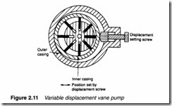
Pumps are generally sold with certain fixed capacities and the user has to choose the next largest size. Figure 2.11 shows a vane pump with adjustable capacity, set by the positional relationship between rotor and inner casing, with the inner casing position set by an external screw.
Piston pumps
A piston pump is superficially similar to a motor car engine, and a simple single cylinder arrangement was shown earlier in Figure 2.2b. Such a simple pump, however, delivering a single pulse of fluid per revolution, generates unacceptably large pressure pulses into the system. Practical piston pumps therefore employ multiple cylinders
and pistons to smooth out fluid delivery, and much ingenuity goes into designing multicylinder pumps which are surprisingly compact.
Figure 2.12 shows one form of radial piston pump. The pump consists of several hollow pistons inside a stationary cylinder block. Each piston has spring-loaded inlet and outlet valves. As the inner cam rotates, fluid is transferred relatively smoothly from inlet port to the outlet port.
The pump of Figure 2.13 uses the same principle, but employs a stationary cam and a rotating cylinder block. This arrangement does not require multiple inlet and outlet valves and is consequently simpler, more reliable, and cheaper. Not surprisingly most radial piston pumps have this construction.
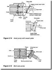
An alternative form of piston pump is the axial design of Figure 2.14, where multiple pistons are arranged in a rotating cylinder. The pistons are stroked by a fixed angled plate called the swash plate. Each piston can be kept in contact with the swash plate by springs or by a rotating shoe plate linked to the swash plate.
Pump capacity is controlled by altering the angle of the swash plate; the larger the angle, the greater the capacity. With the swash plate vertical capacity is zero, and flow can even be reversed. Swash plate angle (and hence pump capacity) can easily be con trolled remotely with the addition of a separate hydraulic cylinder.
An alternative form of axial piston pump is the bent axis pump of Figure 2.15. Stroking of the pistons is achieved because of the angle between the drive shaft and the rotating cylinder block. Pump capacity can be adjusted by altering the drive shaft angle.
Combination pumps
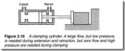
Many hydraulic applications are similar to Figure 2.16, where a workpiece is held in place by a hydraulic ram. There are essentially two distinct requirements for this operation. As the cylinder extends or retracts a large volume of fluid is required at a low pressure (sufficient just to overcome friction). As the workpiece is gripped, the requirement changes to a high pressure but minimal fluid volume.
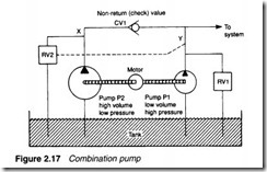
This type of operation is usually performed with two separate pumps driven by a common electric motor as shown in Figure 2.17. Pump P1 is a high pressure low volume pump, while pump P2 is a high volume low pressure pump. Associated with these are two relief valves RV 1 and RV2 and a one-way check (or non-return)
valve which allows flow from left to right, but blocks flow in the reverse direction.
A normal (high pressure) relief valve is used at position RV 1 but relief valve RV2 is operated not by the pressure at point X, but remotely by the pressure at pointY. This could be achieved with the balanced piston valve of Figure 2.6. In low pressure mode both relief valves are closed and both pumps P1 and P2 deliver fluid to the load, the majority coming from pump P2 because of its higher capacity.
When the workpiece is gripped, the pressure at Y rises, and relief valve RV2 opens causing all the fluid from pump P2 to return straight to the tank and the pressure at X to fall to a low value. Check valve CV1 stops fluid from pump P1 passing back to the tank via relief valve RV2, consequently pressure at Y rises to the level set by relief valve RV1• This arrangement saves energy as the large volume of fluid from pump P2 is returned to the tank at a very low pressure, and only a small volume of fluid from pump P1 is returned at a high pressure. Pump assemblies similar to that shown in Figure 2.17 are called combination pumps and are manufactured as complete units with motor, pumps, relief and check valves prefitted.
