Rotary Spool Four- Way Valves
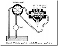
Four-way directional control valves of this type are frequently used as pilot valves to direct flow to and from another valve (Figure 7-30). Fluid is directed from one source of supply through the rotary valve to another directional control valve, where it posi tions the valve to direct flow from another source to one side of an actuating unit. Fluid from the other end of the main valve flows through the return line, through the rotary valve, and to the return line.
The principal parts of a rotary spool valve were shown in Figure 7-19. Figure 7-31 shows the operation of a rotary spool valve. Views A and C show the valve in a posi tion to deliver fluid to another valve, while view B shows the valve in the neutral posi tion, with all passages through the valve blocked.
Sliding Spool Four-Way Valves
The sliding spool four-way valve is similar in operation to the two-way valve previ ously described. It is simple in its operation and is the most durable and trouble-free of all four-way control valves.
The valve (Figure 7-32A) consists of a valve body containing four fluid ports: pres sure (P), return (R), and two cylinder or work ports (Cl and C2). A hollow sleeve fits into the main bore of the valve body. There are static 0-rings placed at intervals around the outside diameter of the sleeve. These 0-rings form a seal between the sleeve and the valve body, creating chambers around the sleeve. Each of these cham bers is lined up with one of the fluid ports in the body.
The drilled passage in the body accounts for a fifth chamber, which results in having two outboard chambers connected to the return port. The sleeve has a pattern of holes drilled through it to allow fluid to flow from one port to another. A series of holes are drilled into the hollow center sleeve in each chamber. The sleeve is prevented from turning by a sleeve retainer bolt or pin that secures it to the valve body.
The sliding spool fits into the hollow center of the sleeve. This spool is similar to the two-way valve, except that this spool has three pistons or lands. These lands are lapped to precisely fit the bore of the sleeve. One or both ends of the spool are con nected to actuators attached to the end of the valve body. These actuators can be mechanical, pneumatic, hydraulic, or electrical. When an actuator is activated, it moves the spool to the desired position. The lands of the spool then line up different combinations of fluid ports and permit fluid flow to the selected ports.
The detent spring is a clothespin-type spring, secured to the end of the body by a spring retaining bolt. The two legs of the spring extend down through slots in the sleeve and fit into the detents. The spool is gripped between the two legs of the spring. To move the spool, enough force must be applied to spread the two spring legs and allow them to snap back into the next detent, which would be for another position.
Figure 7-32, view A, shows a manually operated sliding spool valve in the neutral position. The detent spring is in the center detent of the sliding spool. The center land is lined up with the pressure port (P), preventing fluid from flowing into the valve through this port. The return port is also blocked, preventing flow through that port. With both the pressure and return ports blocked, fluid in the actuating line is trapped. For this reason, a relief valve is usually installed in each actuating line when this type of valve is used.
Figure 7-32, view B, shows the valve in the working position with the end of the slid ing spool retracted. The detent spring is in the outboard detent, locking the sliding spool in this position. The lands have shifted inside the sleeve and the ports are opened. Fluid, under pressure, enters the sleeve, passes through it by way of the drilled holes, and leaves through cylinder port C2. Return fluid flowing from the actu ator enters port Cl, then passes through the return port back to the reservoir. Fluid cannot flow past the spool lands because of the lapped surfaces.
Figure 7-32, view C, shows the valve in the opposite working position with the sliding spool extended. The detent spring is in the inboard detent. The center land of the slid ing spool is now on the other side of the pressure port, and the fluid, under pressure, is directed through the sleeve and out cylinder port C1. Return fluid flows into the valve through cylinder port C2 and returns to the reservoir.
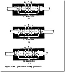
The directional control valves previously discussed are for use in closed-center fluid power systems. Figure 7-33 shows the operation of a representative open-center slid ing spool valve. When this type of valve is in the neutral position (Figure 7-33, view A), fluid flows into the valve through the pressure port (P), through the hollow spool, and returns to the reservoir. When the spool is moved to the right of the neutral posi tion (view B), one working line (Cl) is aligned to system pressure and the other work ing line (C2) is open through the hollow spool to the return port. View C shows the flow of fluid through the valve with the spool moved to the left of neutral position.


