Concepts for estimating pumping energy costs:Flow regulation by varying speed

Flow regulation by varying speed

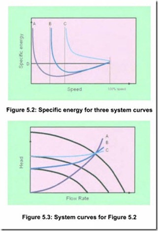
The resulting curves for specific energy as a function of speed for three different system curves are shown in Figure 5.2. Figure 5.3 shows the cor­ responding system curves. The intersection of the two reduced speed pump curves with the system curves B and C, indicate shut off head where the specific energy goes towards infinity. It can be seen that the savings potential is very large at low static head, curve A, whereas care has to be taken in high static head situations, represented by curve C.

When the speed is low enough to cause the pump to operate at or close to shut-off head, the specific energy always goes towards infinity. In case A, this will occur since the motor-drive efficiency will approach zero with no load.

VARIABLE SPEED PUMPING-0737

The line D indicates the specific energy at which the pump is operating when using on-off control. When operating below this line, energy savings will be realized compared to on-off operation.
Related posts:

Energy and Efficiency:Experiments with two level operation
SAFETY VALVES:COOLERS
BASIC DIAGRAMS AND SYSTEMS:FLUID POWER SYSTEMS
Health and safety:Conveying systems and Closed systems.
Material property influences:Conveying modes and Dilute phase non-suspension flow.
Conveying capability:High pressure conveying – Part I
Maintenance and troubleshooting:Cleanliness
Control components in a hydraulic system:Open and closed center hydraulic circuits.
CONTROL VALVES:Rotary Spool Four- Way Valves
Check valves:Pilot-operated check valves and Restriction check valves.
Hydraulic Pumps and Pressure Regulation:Pressure regulation
BASICCONCEPTS OF THE RMODYNAMICS:BAROMETER AND THE ATMOSPHERIC PRESSURE
ENERGY TRANSFER BY HEAT,WORK,AND MASS:NONMECHANICAL FORMS OF WORK
ENTROPY:MINIMIZING THE COMPRESSOR WORK
POWER AND REFRIGER A TION CYCLES:AIR-STANDARD ASSUMPTIONS

Leave a comment

Your email address will not be published. Required fields are marked *