Types of variable speed drive
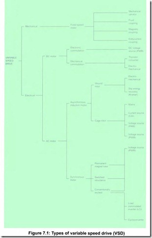
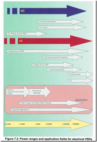
A large number of types of drive are offered for the motor types previously described. Some types of drive, especially electro-mechanical controllers ,are now considered to be outdated technology, but are included for com pleteness (see Figure 7.1). When a motor and a drive are combined, this becomes a power drive system (PDS). The power ranges for different technologies of electrical variable speed drives (VSDs) are shown in Figure 7.2, with a summary of their characteristics and additional details in Appendix A2.
Variable speed drives for induction motors
There are two ways of varying the speed of an induction motor, either by varying the motor slip or by varying the supply frequency.
Whilst it is possible to vary the slip of a conventional cage induction motor by reducing the supply voltage, this introduces unacceptable additional losses manifested as heat in the rotor. Therefore this method is only practical for wound rotor motors where this energy can be dissipated externally.
The preferred practice for electrical speed variation is by changing supply frequency with a variable frequency drive (VFD). The most common form of VFD system is the voltage source pulse width modulation (PWM) frequency converter (often incorrectly referred to as an inverter) applied to a cage induction motor.
Many other designs have been developed. However, few are still offered except for specialised applications.
The frequency converter produces a variable frequency, variable voltage, output waveform. In its simplest form the converter develops a
voltage directly proportional to the frequency, which produces a constant magnetic flux in the motor. If such waveforms are applied to the stator windings there will be a new discrete speed torque relationship for every discrete frequency that can be generated. The motor speed will be propor tional to the frequency generated by the VFD. Figure 7.3 illustrates the effect on a four pole motor operating at three discrete frequencies and showing a typical rotodynamic pump speed torque relationship and a typical positive displacement pump speed torque relationship.
In theory a motor can be driven at any speed between zero and its design (base) speed by maintaining a constant flux. If a higher speed is required, this may be accommodated, providing the motor is appropriately designed. However, as the inverter output voltage will be limited, the motor flux and consequently the available torque will be reduced.
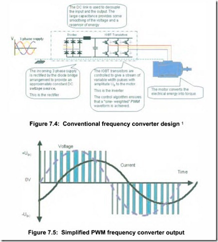
Figure 7.4 shows the design of most frequency converter drive systems. The three-phase AC voltage is initially rectified to a direct current (DC), then smoothed and finally, the DC/AC inverter converts the DC voltage to the variable voltage and variable frequency output applied to the motor. Further details of drive design are described in Appendix A2.1 and A2.2 The pulsed output voltage is applied to the motor and the resulting current, modified by the significant motor inductance, consists mainly of the fundamental sinewave at the required operating frequency with a superimposed low magnitude ripple component based on the switching frequency. Both voltage and current over one cycle are illustrated in simplified form with deliberately reduced switching frequency in Figure 7.5. The voltage and current waveforms are not in phase due to the effects of the motor power factor.


