Radial Piston Pumps
In a radial pump, the cylinder block rotates on a stationary pintle and inside a circular reaction ring or rotor. As the block rotates, centrifugal force, charging pressure, or some form of mechanical action causes the pistons to follow the inner surface of the ring, which is offset from the centerline of the cylinder block. As the pistons reciprocate in their bores, porting in the pintle permits them to take in fluid as they move out ward and discharge it at a higher pressure as they move in.
The size and number of pistons and the length of their stroke determines pump dis placement. In some models, moving the reaction ring to increase or decrease the piston travel length or stroke can vary the displacement.
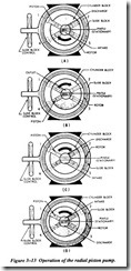
Figure 3-13 illustrates the operation of the radial piston pump. The pump consists of a stationary pintle that acts as a valve and a cylinder block, which revolves around the pin tle. The cylinder block also contains the pistons; a rotor that houses the reaction ring against which the piston heads press; and a slide block that is used to control the length of piston stroke. The slide block does not revolve, but houses and supports the rotor, which does revolve because of the friction set up by the sliding action between the pis ton heads and the reaction ring. The cylinder block is attached to the drive shaft.
Referring to view A of Figure 3-13, assume that space X in one ofthe cylinders of the cylinder block contains fluid and that the respective piston of this cylinder is at position 1. When the cylinder block and piston are rotated in a clockwise direction, the piston is forced into its cylinder as it approaches position 2. This action reduces the volumetric size of the cylinder and forces a quantity of fluid out of the cylinder and into the outlet port above the pintle. This pumping action is due to the rotor being off center in relation to the center of the cylinder block.
In Figure 3-13, view B, the piston has reached position 2 and has forced the fluid out of the open end of the cylinder, through the outlet above the pintle and into the sys tem. While the piston moves from position 2 to position 3, the open end of the cylin der passes over the solid part of the pintle; therefore, there is no intake or discharge of fluid. As the piston and cylinder move from position 3 to position 4, centrifugal force causes the piston to move outward against the reaction ring of the rotor. During this time the open end of the cylinder is open to the intake side of the pintle and fills with fluid. As the piston moves from position 4 to position I, the open end of the cylinder is against the solid side of the pintle and no intake or discharge of fluid takes place. After the piston has passed the pintle and starts toward position 2, another discharge of fluid takes place. Alternate intake and discharge continues as the rotor revolves about its axis-intake on one side of the pintle and discharge on the other.
Notice in views A and B of Figure 3-13 that the center point of the rotor is different from the center point of the cylinder block. The difference of these centers produces the pumping action. If the rotor is moved so that its center point is the same as that of the cylinder block, as shown in Figure 3-13, view C, there is no pumping action. Since the piston does not move back and forth in the cylinders as it rotates within the cylin der block, no pumping can take place.
The flow in this pump can be reversed by moving the slide block and rotor to the right so the relation of the centers of the rotor and cylinder block is reversed from the posi tion shown in views A and B of Figure 3-13. View D shows this arrangement. Fluid enters the cylinder as the piston travels from position 1 to position 2 and is discharged from the cylinder as the piston travels from position 3 to position 4.
In the illustrations, the rotor is shown in the center, the extreme right, or the extreme left as related to the cylinder block. The amount of adjustment in distance between the two centers determines the length of the piston stroke and the amount of fluid flow in and out of the cylinder. Thus, the adjustment determines the displacement of the pump. This adjustment may be controlled in different ways. Manual control by a handwheel is the simplest. The pump illustrated in Figure 3-13 is controlled in this way. For automatic control of delivery to accommodate varying volume requirements during the operating cycle, a hydraulically controlled cylinder may be used to position the slide block. A gear motor controlled by a push button or a limit switch is some times used for this purpose.
Swash Plate Design Pumps
In axial piston pumps, the cylinder block and drive shaft are on the same centerline and the pistons reciprocate parallel to the drive shaft. The simplest type of axial piston pump is the swash plate inline design (Figure 3-15).
The cylinder blow in this pump is turned by the drive shaft. Pistons fitted to bores in the cylinder are connected through piston shoes and a retracting ring, so that the shoes bear against an angled swash plate. As the block turns (Figure 3-16), the piston shoes follow the swash plate, causing the pistons to reciprocate. The ports are arranged in
the valve plate so that the pistons pass the inlet as they are being pulled out and pass the outlet as they are being forced forward.
In these pumps the size and number of pistons as well as their stroke length also deter mine the displacement. The stroke length is controlled by the swash plate angle. In variable-displacement models, the swash plate is installed in a movable yoke (Figure 3-17). By pivoting the yoke on pintles, the swash plate angle and piston stroke can be increased or decreased. Figure 3-17 shows a compensator control, but the angle can also be controlled manually or by a variety of other means.
Operation of the inline compensator-controlled pump is shown schematically in Figure 3-17. The control consists of a compensator valve balanced between load pressure and the force of a spring, a piston controlled by the valve to move the yoke, and a yoke return
spring.With no outlet pressure, the yoke return spring moves the yoke to the full-delivery position .As pressure builds, it acts against the end of the valve spool. When the pressure is high enough to overcome the valve spring, the spool is displaced and oil enters the yoke piston. The piston is forced by the oil under pressure to decrease the pump displacement. If the pressure falls off, the spool automatically moves back, oil is discharged from the pis ton to the inside of the pump casing, and the spring returns the yoke to a greater angle.
The compensator adjusts the pump outlet to whatever displacement is required to develop and maintain the preset pressure. This prevents excess power loss by avoiding relief valve operation at full pump volume in holding and clamping applications.


