FLOW ACROSS CYLINDERS AND SPHERES
Flows across cylinders and spheres, in general, involve flow separation, which is difficult to handle analytically. Therefore, such flows must be studied experimentally or numerically. Indeed, flow across cylinders and spheres has been studied experimentally by numerous investigators, and several empirical correlations have been developed for the heat transfer coefficient.
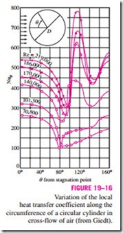
The complicated flow pattern across a cylinder greatly influences heat transfer. The variation of the local Nusselt number Nuu around the periphery of a cylinder subjected to cross flow of air is given in Fig. 19–16. Note that, for all cases, the value of Nuu starts out relatively high at the stagnation point (u = 0°) but decreases with increasing u as a result of the thickening of the laminar boundary layer. On the two curves at the bottom corresponding to Re = 70,800 and 101,300, Nuu reaches a minimum at u = 80°, which is the separation point in laminar flow. Then Nuu increases with increasing u as a result of the intense mixing in the separated flow region (the wake). The curves at the top corresponding to Re = 140,000 to 219,000 differ from the first two curves in that they have two minima for Nuu. The sharp increase in Nuu at about u = 90° is due to the transition from laminar to turbulent flow. The later decrease in Nuu is again due to the thickening of the boundary layer. Nuu reaches its second minimum at about u = 140°, which is the flow separation point in turbulent flow, and increases with u as a result of the intense mixing in the turbulent wake region.
The discussions above on the local heat transfer coefficients are insightful; however, they are of little value in heat transfer calculations since the calculation of heat transfer requires the average heat transfer coefficient over the entire surface. Of the several such relations available in the literature for the average Nusselt number for cross-flow over a cylinder, we present the one proposed by Churchill and Bernstein:
This relation is quite comprehensive in that it correlates available data well for Re Pr > 0.2. The fluid properties are evaluated at the film tempera- ture Tf = 1 (Tx + Ts), which is the average of the free-stream and surface temperatures.
For flow over a sphere, Whitaker recommends the following comprehensive correlation:
which is valid for 3.5 < Re < 80,000 and 0.7 < Pr < 380. The fluid proper- ties in this case are evaluated at the free-stream temperature Tx, except for ms, which is evaluated at the surface temperature Ts. Although the two relations above are considered to be quite accurate, the results obtained from them can be off by as much as 30 percent.
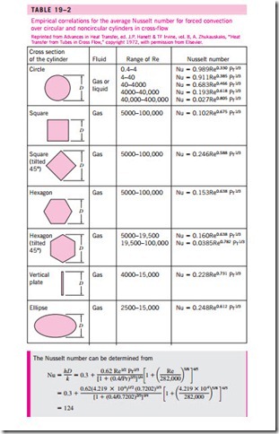
The average Nusselt number for flow across cylinders can be expressed compactly as
where n = 1 and the experimentally determined constants C and m are given in Table 19–2 for circular as well as various noncircular cylinders. The characteristic length D for use in the calculation of the Reynolds and the Nusselt numbers for different geometries is as indicated on the figure. All fluid properties are evaluated at the film temperature.
The relations for cylinders above are for single cylinders or cylinders oriented such that the flow over them is not affected by the presence of others. Also, they are applicable to smooth surfaces. Surface roughness and the free- stream turbulence may affect the drag and heat transfer coefficients significantly. Eq. 19–30 provides a simpler alternative to Eq. 19–28 for flow over cylinders. However, Eq. 19–28 is more accurate, and thus should be preferred in calculations whenever possible.
