Introduction to pneumatic conveying and the guide:Nomenclature

Nomenclature

The notation used throughout the book is given here for general reference as it presents the style adopted and the form of SI units used in one place. Where equations are developed in the book an abbreviated notation will also be given for reference at the point of use.

Introduction to pneumatic conveying and the guide-0005Introduction to pneumatic conveying and the guide-0006

Introduction to pneumatic conveying and the guide-0007

Note

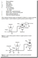
(a) In a negative pressure system, p1 will be slightly below atmospheric pressure if an artificial resistance is added to the air supply pipeline inlet for the purpose of assisting the feed of material into the pipeline; p2 and T2 will generally be equal to p3 and T3; but the mass flow rate of air at 3 might be higher than that at 2 if there is a leakage of air across the material outlet valve on the discharge hopper.

(b) In a positive pressure system; p1 will generally be equal to p4 unless there is a pressure drop across the feeding device; p2 and p3 will generally be equal to the local atmospheric pressure; and the mass flow rate of air at 1 will be lower than that at 4 if there is a leakage of air across the feeding device.

Incoming search terms:

Related posts:

Actuators:selection and performance of cylinders
Energy and Efficiency:Theory of two level systems
Energy and Efficiency:PIPE FLOW CALCULATIONS
CONTROL VALVES:Globe Valves
Low pressure and vacuum:Discharge period and pulsations and Positive pressure systems.
Fine material:Dense phase conveying of cement
Design procedures:Logic diagram for system capability and Specify bounding conditions
Conveying capability:High pressure conveying – Part IV
Conveying characteristics:Component pressure drop relationships
HYDRAULIC PUMPS:Wobble Plate Inline Pumps and Bent Axis Pumps.
Control components in a hydraulic system:Servo valves
Hydraulic accumulators.
BASICCONCEPTS OF THE RMODYNAMICS:TEMPERATURE AND THE ZEROTH LAW OF THERMODYNAMICS
SUMMARY OF ENERGY TRANSFER BY HEAT,WORK,AND MASS
POWER AND REFRIGER A TION CYCLES:THE IDEAL VAPOR-COMPRESSION REFRIGERATION CYCLE

Leave a comment

Your email address will not be published. Required fields are marked *