■ THE CARNOT VAPOR CYCLE
We have mentioned repeatedly that the Carnot cycle is the most efficient cycle operating between two specified temperature limits. Thus it is natural to look at the Carnot cycle first as a prospective ideal cycle for vapor power plants. If we could, we would certainly adopt it as the ideal cycle. As explained here, however, the Carnot cycle is not a suitable model for power cycles. Through- out the discussions, we assume steam to be the working fluid since it is the working fluid predominantly used in vapor power cycles.
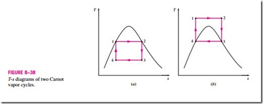
Consider a steady-flow Carnot cycle executed within the saturation dome of a pure substance, as shown in Fig. 8–38a. The fluid is heated reversibly and isothermally in a boiler (process 1-2), expanded isentropically in a turbine (process 2-3), condensed reversibly and isothermally in a condenser (process 3-4), and compressed isentropically by a compressor to the initial state (process 4-1).
Several impracticalities are associated with this cycle:
1. Isothermal heat transfer to or from a two-phase system is not difficult to achieve in practice since maintaining a constant pressure in the device will automatically fix the temperature at the saturation value. Therefore, processes 1-2 and 3-4 can be approached closely in actual boilers and condensers. Limiting the heat transfer processes to two-phase systems, however, severely limits the maximum temperature that can be used in the cycle (it has to remain under the critical-point value, which is 374˚C for water). Limiting the maxi- mum temperature in the cycle also limits the thermal efficiency. Any attempt to raise the maximum temperature in the cycle will involve heat transfer to the working fluid in a single phase, which is not easy to accomplish isothermally.
2. The isentropic expansion process (process 2-3) can be approximated closely by a well-designed turbine. However, the quality of the steam de- creases during this process, as shown on the T–s diagram in Fig. 8–38a. Thus the turbine will have to handle steam with low quality, that is, steam with a high moisture content. The impingement of liquid droplets on the turbine blades causes erosion and is a major source of wear. Thus steam with qualities less than about 90 percent cannot be tolerated in the operation of power plants. This problem could be eliminated by using a working fluid with a very steep saturated vapor line.
3. The isentropic compression process (process 4-1) involves the compression of a liquid–vapor mixture to a saturated liquid. There are two difficulties associated with this process. First, it is not easy to control the condensation process so precisely as to end up with the desired quality at state 4. Second, it is not practical to design a compressor that will handle two phases.
Some of these problems could be eliminated by executing the Carnot cycle in a different way, as shown in Fig. 8–38b. This cycle, however, presents other problems such as isentropic compression to extremely high pressures and isothermal heat transfer at variable pressures. Thus we conclude that the Carnot cycle cannot be approximated in actual devices and is not a realistic model for vapor power cycles.
