PRESSURE
Pressure is defined as the force exerted by a fluid per unit area. We speak of pressure only when we deal with a gas or a liquid. The counterpart of pressure in solids is stress. Since pressure is defined as force per unit area, it has the unit of newtons per square meter (N/m2), which is called a pascal (Pa). That is,
The pressure unit pascal is too small for pressures encountered in practice. Therefore, its multiples kilopascal (1 kPa = 103 Pa) and megapascal (1 MPa = 106 Pa) are commonly used. Three other pressure units commonly used in practice, especially in Europe, are bar, standard atmosphere, and kilogram-force per square centimeter:
Note the pressure units bar, atm, and kgf/cm2 are almost equivalent to each other. In the English system, the pressure unit is pound-force per square inch (lbf/in2, or psi), and 1 atm = 14.696 psi. The pressure units kgf/cm2 and lbf/in2 are also denoted by kg/cm2 and lb/in2, respectively, and they are commonly used in tire gages. It can be shown that 1 kgf/cm2 = 14.223 psi.
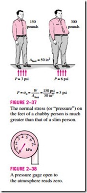
Pressure is also used for solids as synonymous to normal stress, which is force acting perpendicular to the surface per unit area. For example, a 150-pound person with a total foot imprint area of 50 in2 will exert a pressure of 150/50 = 3.0 psi. If the person stands on one foot, the pressure will double (Fig. 2–37). If the person gains excessive weight, he or she is likely to en- counter foot discomfort because of the increased pressure on the foot (the size of the foot does not change with weight gain). This also explains how a per- son can walk on fresh snow without sinking by wearing large snowshoes, and how a person cuts with little effort when using a sharp knife.
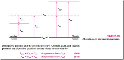
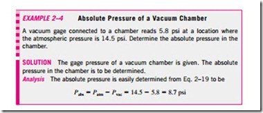
is measured relative to absolute vacuum (i.e., absolute zero pressure). Most pressure-measuring devices, however, are calibrated to read zero in the atmosphere (Fig. 2–38), and so they indicate the difference between the absolute pressure and the local atmospheric pressure. This difference is called the gage pressure. Pressures below atmospheric pressure are called vacuum pressures and are measured by vacuum gages that indicate the difference between the
This is illustrated in Fig. 2–39.
Like other pressure gages, the gage used to measure the air pressure in an automobile tire reads the gage pressure. Therefore, the common reading of 32 psi (2.25 kgf/cm2) indicates a pressure of 32 psi above the atmospheric pres- sure. At a location where the atmospheric pressure is 14.3 psi, for example, the absolute pressure in the tire will be 32 + 14.3 = 46.3 psi.
In thermodynamic relations and tables, absolute pressure is almost always used. Throughout this text, the pressure P will denote absolute pressure unless specified otherwise. Often the letters “a” (for absolute pressure) and “g” (for gage pressure) are added to pressure units (such as psia and psig) to clarify what is meant.
Pressure at a Point
Pressure is the compressive force per unit area, and it gives the impression of being a vector. However, pressure at any point in a fluid is the same in all
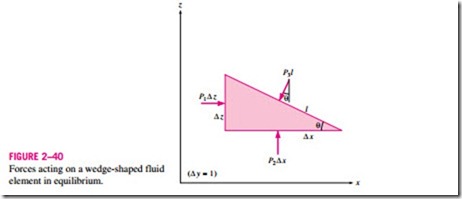
directions. That is, it has magnitude but not a specific direction, and thus it is a scalar quantity. This can be demonstrated by considering a small wedge- shaped fluid element of unit length (into the paper) in equilibrium, as shown in Fig. 2–40. The mean pressures at the three surfaces are P1, P2, and P3, and the force acting on a surface is the product of mean pressure and the surface area. From Newton’s second law, a force balance in the x– and z-directions gives
where p is the density and W = mg = pg x z/2 is the weight of the fluid element. Noting that the wedge is a right triangle, we have x = l cos e and z = l sin e. Substituting these geometric relations and dividing Eq. 2–20a by z and Eq. 2–20b by x gives
regardless of the angle e. We can repeat the analysis for an element in the xz-plane, and obtain a similar result. Thus we conclude that the pressure at a point in a fluid has the same magnitude in all directions. It can be shown in the absence of shear forces that this result is applicable to fluids in motion as well as fluids at rest.
Variation of Pressure with Depth
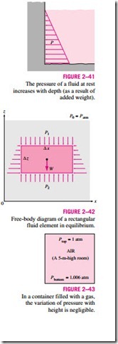
It will come as no surprise to you that pressure in a fluid does not change in the horizontal direction. This can be shown easily by considering a thin horizontal layer of fluid, and doing a force balance in any horizontal direction. However, this is not the case in the vertical direction in a gravity field. Pressure in a fluid increases with depth because more fluid rests on deeper layers, and the effect of this “extra weight” on a deeper layer is balanced by an increase in pressure (Fig. 2–41).
To obtain a relation for the variation of pressure with depth, consider a rec- tangular fluid element of height �z, length �x, and unit depth (into the paper) in equilibrium, as shown in Fig. 2–42. Assuming the density of the fluid r to be constant, a force balance in the vertical z-direction gives
where ” { = rg is the specific weight of the fluid. Thus, we conclude that the pressure difference between two points in a constant density fluid is proportional to the vertical distance z between the points and the density r of the fluid. In other words, pressure in a fluid increases linearly with depth. This is what a diver will experience when diving deeper in a lake. For a given fluid, the vertical distance z is sometimes used as a measure of pressure, and it is called the pressure head.
We also conclude from Eq. 2–24 that for small to moderate distances, the variation of pressure with height is negligible for gases because of their low density. The pressure in a tank containing a gas, for example, can be consid- ered to be uniform since the weight of the gas is too small to make a significant difference. Also, the pressure in a room filled with air can be assumed to be constant (Fig. 2–43).
If we take point 1 to be at the free surface of a liquid open to the atmosphere, where the pressure is the atmospheric pressure Patm, then the pressure at a depth h from the free surface becomes Free-body diagram of a rectangular fluid element in equilibrium.
Liquids are essentially incompressible substances, and thus the variation of density with depth is negligible. This is also the case for gases when the elevation change is not very large. The variation of density of liquids or gases with temperature can be significant, however, and may need to be considered when high accuracy is desired. Also, at great depths such as those encountered in oceans, the change in the density of a liquid can be significant because of the compression by the tremendous amount of liquid weight above.
The gravitational acceleration g varies from 9.807 m/s2 at sea level to 9.764 m/s2 at an elevation of 14,000 m where large passenger planes cruise. This is a change of just 0.4 percent in this extreme case. Therefore, g can be assumed to be constant with negligible error.
For fluids whose density changes significantly with elevation, a relation for the variation of pressure with elevation can be obtained by dividing Eq. 2–23 by x z, and taking the limit as z → 0. It gives
The negative sign is due to our taking the positive z direction to be upward so that dP is negative when dz is positive since pressure decreases in an upward direction. When the variation of density with elevation is known, the pressure difference between points 1 and 2 can be determined by integration to be
For constant density and constant gravitational acceleration, this relation reduces to Eq. 2–24, as expected.
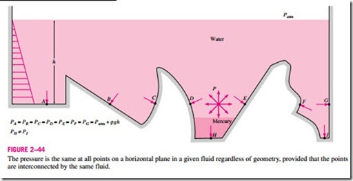
Pressure in a fluid is independent of the shape or cross section of the container. It changes with the vertical distance, but remains constant in other directions. Therefore, the pressure is the same at all points on a horizontal plane in a given fluid. This is illustrated in Fig. 2–44. Note that the pressures at points A, B, C, D, E, F, and G are the same since they are at the same depth, and they are interconnected by the same fluid. However, the pressures at points H and I are not the same since these two points cannot be interconnected by the same fluid (i.e., we cannot draw a curve from point I to point H while remaining in the same fluid at all times), although they are at the same depth. (Can you tell at which point the pressure is higher?) Also, the pressure force exerted by the fluid is always normal to the surface at the specified points.
A consequence of the pressure in a fluid remaining constant in the horizon- tal direction is that the pressure applied to a confined fluid increases the pressure throughout by the same amount. This is called Pascal’s principle, after Blaise Pascal (1623–1662). Pascal’s principle, together with the fact that the pressure force applied by a fluid at a surface is proportional to the surface area, has been the source of important technological innovations. It has reulted in many inventions that impacted many aspects of ordinary life such as hydraulic brakes, hydraulic car jacks, and hydraulic lifts. This is what enables us to lift a car easily by one arm, as shown in Fig. 2–45. Noting that P1 = P2
since both pistons are at the same level (the effect of small height differences is negligible, especially at high pressures), the ratio of output force to input force is determined to be
The area ratio A2/A1 is called the ideal mechanical advantage of the hydraulic lift. Using a hydraulic car jack with a piston area ratio of A2/A1 = 10, for example, a person can lift a 1000-kg car by applying a force of just 100 kgf (= 908 N).

