Volumetric flow rate
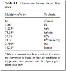
Volumetric flow rate in m3/s has been chosen for all mathematical models presented as it is the basic SI unit. On graphical plots, however, m3/min has been used as it is more widely quoted in trade literature for blowers and compressors. Conversion factors to and from m3/s for other units are presented in Table 9.1.
Divide by the numbers given in Table 9.1 to convert the other way round. This point will be considered further in the next section.
Presentation of equations
The majority of the equations that follow are presented in terms of both volumetric flow rate and conveying air velocity. The reason for this is the need to provide models that can be used for both the design of future systems and for checking the operation of existing systems.
In the design of a system a specific value of conveying air velocity will generally be recommended, together with a pipe bore, and it is the value of volumetric flow rate that is required for specification of the blower or compressor. In order to check an existing system it is usually necessary to determine the conveying air velocity for the particular conditions.
In addition to providing the appropriate models for the evaluation of air requirements and conveying air velocities, graphical representation of these models is also presented. With programmable calculators and computers, models such as these can be handled quite easily and quickly. Graphs, however, do have the advantage of showing visually the relative effects of the various parameters, and in some cases can be used very effectively to illustrate particular processes.
The influence of pipe bore
The diameter of a pipeline probably has the most significant effect of any single parameter on volumetric flow rate. The volumetric flow rate through a pipeline depends upon the mean velocity of flow at a given point in the pipeline and the pipe section area. The relationship is:
A graphical representation of the above models is presented in Figure 9.2. This is a plot of volumetric air flow rate against conveying air velocity, with a series of lines representing the relationship for different sizes of pipe. Conveying air velocities from about 2 to 40 m/s have been considered in order to cover the two extremes of minimum velocity in dense phase conveying and maximum velocity in dilute phase conveying. With pipeline bore as the family of curves this is a linear relationship.
Reference conditions
It should be noted that the volumetric flow rate on this graph is not related to any reference conditions. It is the actual flow rate at any given condition of air pressure and temperature. Equations (9.1)–(9.3) and Figure 9.2 can be used either to determine the resulting velocity for a given flow rate in a given pipe size, or to determine the required volumetric flow rate knowing the velocity and pipe size.
Blowers and compressors are usually rated in terms of ‘free air delivered’. This means that the volumetric flow rate is related to ambient conditions for reference purposes – usually a pressure of 1.013 bar absolute and a temperature of 15°C (288 K). The influence of pressure and temperature on volumetric flow rate, and hence velocity, is discussed in the following sections.
Pipeline influences
The air at the start of a conveying line will always be at a higher pressure than that at the end of the line because of the pressure drop necessary for air and material flow. Density decreases with decrease in pressure and so, in a constant bore pipeline, the air velocity will gradually increase from the start to the end of the pipeline. The air mass flow rate will remain constant at any section along a pipeline, but as the rating of blowers and compressors is generally expressed in volumetric flow rate terms, know- ledge of the air mass flow rate is of little value in this situation.


