Water vapour
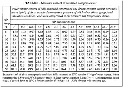
Ambient air always contains water vapour. After it leaves the compressor, it is fully saturated with water vapour, the actual amount present being directly proportional to the temperature and inversely proportional to the pressure, see Table 5. The liquid water is best removed when the temperature of the air is lowest and the pressure is highest,
Example: I m3 of air at atmospheric conditions fully saturated at 20°C contains 17.4 g of water vapour. When compressed to 6.3 bar and 50°C it can only retain 11.2 gas vapour, therefore 6.2 g ( 17.4 – 11.2) is released as liquid water. If cooled down to 25°C a further quantity of 7.93 g ( 11.2- 3.27) of water will condense out.
ie immediately after the compressor and its aftercooler. Standard practice is to follow the compressor element with an after cooler of sufficient capacity to reduce the temperature to within 10°C of the temperature of the cooling water or air. In the former case, approximately 20 litres of water will be required for every 2.5 m3 of free air being cooled. Further cooling is possible if a reasonably large receiver is fitted.
Refer to the chapter on Air Receivers to assess the proper volume. It is often quoted that the size of the receiver should be approximately equal to 30 times the rated free air deli very of the compressor, for 7 bar applications. A receiver should incorporate a condensate drain, preferably of an automatic type.
Further cooling is likely to occur in the distribution main, so these should be laid out with a pitch in the direction of flow so that gravity and air flow will carry the water to drain legs, located at appropriate intervals. These also should be fitted with automatic drain valves to prevent them being flooded. Down loops in the distribution main should be avoided where possible, but if this cannot be avoided, they mustincorporatedrain legs at the bottom of the down loop. All take-off points from the distribution main should be located at the top of the main to prevent water getting into the take-off line.
