Synthesised tuning
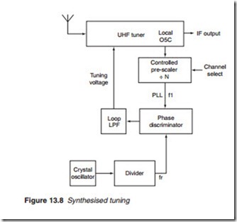
Synthesis is the process of combining or adding up incremental amounts to obtain a certain quantity of, say, a voltage or a frequency. In the frequency synthesised tuner (FST), the tuning voltage is obtained from a programmable PLL composed of the tuner’s local oscillator, a controlled pre-scaler, a phase discriminator and a low-pass filter (Figure 13.8). A sample of the tuner’s local oscillator frequency is fed back to the phase discriminator via a controlled divider (divide by N ), known as a pre-scaler. The value of N is set by the channel select input which determines the frequency f1 going into the phase discriminator. The discriminator then compares f1 with reference frequency fr. A d.c. output is produced that reflects the difference between the two frequencies. After filtering, this d.c. voltage is used to tune the tuner to the selected channel. Synthesised PLL-controlled tuners have extremely stable output with practically no drift, thus removing the need
for an a.f.c. circuit. The stability of the tuner output depends to a large extent on the stability of the reference frequency. For this reason, a fre- quency divider is used to divide the frequency of a crystal-controlled ref- erence oscillator by a large factor to improve its stability.
The IF stage
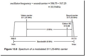
Recall that the IF is derived at the mixer-oscillator stage of the tuner. The local oscillator is made to oscillate at a frequency which is 39.5 MHz higher than the selected carrier frequency. The IF is then obtained by selecting the difference between the carrier and the oscillator frequencies. For exam- ple, if the TV receiver is tuned to a channel frequency of 511.25 MHz (BBC 1 transmission from Crystal Palace) then the oscillator must be tuned to frequency fo = 511.25 + 39.5 = 550.75 MHz. The relative position of the var- ious frequencies of a modulated UHF carrier may be observed on a spec- trum analyser such as that illustrated in Figure 13.9 for a modulated 511.25 MHz carrier. The 8 MHz bandwidth extends from fmin to fmax where
The sound carrier is 6 MHz above the vision carrier, so it has a frequency of 511.25 + 6.00 = 517.25 MHz.
After the mixer-oscillator stage, the vision carrier is replaced by a vision IF of 39.5 MHz with RF oscillator frequency of 511.25 + 39.5 = 550.75 MHz.
The sound carrier is translated into a sound IF of
The sound IF is now 6 MHz below the vision IF Similarly, all other frequencies will reverse their position relative to the vision carrier when they are converted to their equivalent on the IF spectrum.


