SOUND DEMODULATION
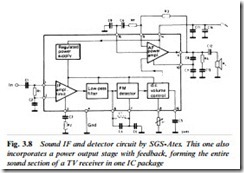
Since the deviation of the sound carrier (now in 6 MHz form) is ±50 kHz, a sharply tuned circuit with at least 100 kHz bandwidth, and centred on 6 MHz, is required to filter out the sound carrier from the video waveform. It takes the form of a ceramic filter, a very small mechanical resonator with sharp cut-off characteristics. After pass- ing through one or two of these the sound carrier is ‘clean’ and ready for delivery to its demodulator. First (Figure 3.8) it passes through several limiter stages, in which it is repeatedly amplified and clipped to remove all traces of amplitude modulation, and with them the influence of interference spikes and noise. The sound detector is also a synchronous type, but here working in quadrature mode, with the 6 MHz tank coil L1 adjusted so that the carrier-sampling pulses are 90° out of phase with the cycles of the unmodulated carrier. The output from this arrangement is proportional to phase angle of the sound carrier, which is what is required for f.m. demodulation. A preamplifier within the IC brings the level up to the 0 dB (0.775 V r.m.s.) point, or indeed any other required level; its gain is adjustable in many chip designs by virtue of an internal voltage-controlled attenuator (VCA). By this means sound level can be controlled by application of a variable d.c. voltage, useful for local control and mut- ing purposes and essential for remote control applications. In Fig.
3.8 the VCA is controlled via pin 8 of the chip.
The sound limiting, demodulator and initial amplifier stages are
often incorporated in the same IC as the vision section shown in Fig. 3.7, together with many other functions. Again the dedicated chip shown here gives a better insight into the principles involved.
FREQUENCY-SYNTHESIS TUNING
Since the received channel depends purely on the frequency of the local oscillator within the tuner, and since broadcast transmissions – be they from terrestrial or space-based transmitters – are held very accurately to their nominal frequencies, there is no theoretical need for any trial-and-error tuning systems. Very accurate and stable crystal control of the receiver’s local oscillator would suffice for a fixed-tuning system. In practical frequency-synthesis tuning systems the ‘analogue’ oscillator is still present within the tuner, and still controlled by a d.c. potential acting on an array of varicap diodes. Here, however, the oscillator is made part of a phase-lock-loop (PLL) in which it comes under the influence of a stable local frequency reference in the form of a quartz crystal.
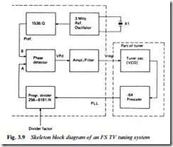
A basic block diagram is given in Fig. 3.9. Inside or adjacent to the tuner is a prescaler which divides the local oscillator frequency fosc by 64, and is capable of working with input frequencies up to 1 GHz (1000 MHz). The counted-down frequency is fosc/64, and this
is applied to an LSI (Large Scale Integration) digital IC called a programmable divider which further divides fosc/64 by a factor determined by its programming instructions. Their derivation will be described shortly. Thus at the phase detector’s ‘A’ input appears a signal frequency which depends on (a) the tuner’s local oscillator frequency, and (b) the division ratio of the programmable divider. At the top of the diagram appears a reference crystal oscillator run- ning at 3 MHz and feeding a fixed divider (counter) whose division ratio is fixed at 1536. 3 MHz divided by 1536 is 1.953 kHz and this is the frequency applied to the ‘B’ input of the phase detector. Whenever the frequency or phase of the A and B inputs differ the phase detector produces a d.c. error output whose polarity is depend- ent on the direction of the error (i.e. whether B input is faster or slower than A input); and whose magnitude is proportional to the difference in speeds between the two inputs. The error voltage is amplified and filtered and appears as a control potential on the tuner’s varicap control line. Since the local oscillator is in effect a VCO (Voltage-Controlled Oscillator) its frequency changes until the two inputs of the phase detector come into frequency and phase coincidence, when the varicap control potential stabilises. What we have set up is a phase-lock-loop (PLL) in which fosc is locked to a multiple of the 3 MHz crystal reference, the exact multiple being set by the division ratio of the programmable divider (PD) block. In fact the PD can divide by numbers between 256 and 8191.
To set a required channel, then, we merely give the divider a coded instruction to correspond with the known and preprogrammed chan- nel frequency. We know that the local oscillator must run 39.5 MHz above incoming r.f. and we know the CCIR standard vision carrier frequencies for each TV channel. Taking a numerical example, sup- pose it is required to tune channel 41 whose vision carrier is 631.25 MHz. Required tuner fosc is 631.25 + 39.5 = 670.75 MHz, giving rise to 10.48 MHz from the prescaler. To satisfy the 1.953 kHz input requirement of the phase detector we need to set a division ratio in the PD of the 10480/1.953 = 5366. This ratio is one of, say, 100 available to cover all CCIR-approved TV channels on the four bands available to terrestrial transmissions. Each channel instruc- tion is held in a ROM (read-only memory) as a group of thirteen binary digits (bits), and for the channel 41 division ratio of 5366 the binary code happens to be 1010011110001. For UHF channel 64 the division ratio is 6838 and the corresponding binary code 1101010110001.
The ROM needs in this case to have 100 memory addresses with the appropriate code for the division ratio for each possible channel permanently stored there. Thus (in simple terms) if channel 41 is requested on the user’s keypad, address no. 41 will be accessed and its contents 1010011110001 read out into the instruction register of the programmable divider. Some of the digits contain bandswitching instructions (not currently needed in the UK except for a satellite receiver option) which are decoded and passed to the tuner(s) to enable the appropriate section to operate.
Most frequency-synthesis tuning systems have facilities for sweep- search. An alternative name for it is self-seek, and when this function is invoked the control system steps through the 100 addresses in the programme ROM sequentially, presenting their contents in turn to the programmable divider. The tuner is thus stepped through all available transmission channels in its search for a broadcast transmission. When one is found the TV’s line oscillator quickly synchronises to it: an output pin on the line generator chip signals ‘locked’ to the tuning control microcomputer, instructing it to stop seeking. What happens next depends on the user’s requirements. If he wishes the set to memorise that channel, a touch of the ‘memory’ button will write the PD instructions into a RAM (Random Access Memory) for instant call-up when that channel is next required. These binary- coded instructions may typically be held at ‘Address 1’ in the RAM and contain data corresponding to the local BBC 1 transmission channel. Further seeking will find the other local channels and the output channels of other equipment like videorecorders, TV games and home computers, and each can be assigned to memory in turn. This memory store (EEPROM, Electrically Erasable Programmable Read-Only Memory) is built in ‘floating gate technology’ which means that the data is held in the form of electrostatic charges in the isolated gate regions of an array of FETs (Field Effect Transistors). Such a memory is called non-volatile because the data can be held for several years without any need for external power. This type of memory is ideal for TV channel data storage in a set which may not be continuously powered. In fact the contents can be erased and over- written by means of applying a high ‘erase voltage’ of +33 V, and this is carried out whenever the user or installer re-programmes the memory.
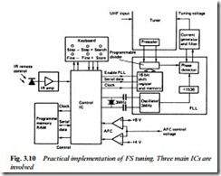
A basic block diagram of the synthesis control system is given in Fig. 3.10. The need for a.f.c. control may well be questioned in view of the accuracy and stability of the crystal reference. In fact none is needed for broadcast transmissions, but the r.f. modulators fitted to home computers and video recorders can drift in frequency, and will probably not produce a vision carrier exactly on the frequency specified for a CCIR channel. Hence the ‘fine tune minus’ and ‘fine tune
plus’ buttons. Plainly, continuous tuning is not possible with a frequency synthesis system, but very small discrete steps can be made. In the present case the (divided) reference frequency of 1.953 kHz and prescaler division factor of 64 gives a minimum step of 1.953 × 64 = 125 kHz, sufficient for 64 separate tuning points across one 8 MHz wide television channel; to all intents and purposes this approximates to continuous tuning.
A further development of microprocessor tuning control is auto- set-up, in which the receiver sweep-tunes by itself to sample the avail- able signals, memorises their tuning points and assigns them memory slots in order. It will be dealt with in more detail in Chapter 22.


