TELETEXT DECODER
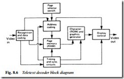
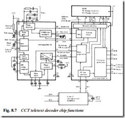
Fig. 8.6 shows the essentials of a teletext decoder, and Fig. 8.7 a two- chip decoder, now superseded, but better than later systems as a model for explaining the system. It uses, in addition to the two decoder ICs, a RAM (Random Access Memory) and optional on-board dedicated control microprocessor. It is governed by a two- wire serial control bus SDA and SCL, which will be fully explained in Chapter 22. Suffice it here to say that all the user’s commands via the remote control handset are communicated by the data on the bus. Video signals enter the VIP (Video Input Processor) SAA5230 at pin 27 and take two routes: to a sync separator, and via conditioning circuitry to an adaptive data slicer, which sets the level (half peak eyeheight) at which the decision between 0 and 1 symbols are made – this gives some immunity to noise and interference. Taking the sync path first, off-air sync pulses form one input to a phase detector; the other is in the form of a sandcastle pulse from a divider in the CCT chip SAA5240. The resultant output from the phase detector steers the frequency and phase of a 6 MHz dot oscillator which drives both the divider chain (to complete the PLL) and the display generator in the CCT chip. Thus the character display on screen is synchronised with the off-air picture, vital for subtitles and text/picture mixing.
The second function of the VIP IC is to produce a 6.9 MHz text clock for the synchronous detector inside the CCT chip; it is generated by the phase-controlled 13.8 MHz crystal at pin 11, and passed out of the IC on pin 14. Summing up the functions of the analogue SAA5230, then, it provides four essential feeds for the wholly digital
chip SAA5240: a broadcast-synchronised display-dot timing clock; a sync-pulse train locked to the broadcast; the text data pulse-train, sliced at the optimum point; and to go with it, a 6.9 MHz data clock to time its acquisition and decoding. In the absence of a broadcast (‘after-hours’), the sync and dot-clock pulse trains continue, now self- generated, to permit stable display of the text page(s) stored in memory.
At this stage nothing has been captured, memorised or displayed. These are the functions of the second chip, CCT (Computer- Controlled Teletext) SAA5240. It must receive the viewer’s instructions, primarily the required page number; capture and detect that page’s data when it is broadcast; write it into memory and update the latter each time the page comes round again; continually read from the same memory at normal (625/50) scanning rate; convert the data readout into character pulse-trains for R, G and B; and inject them into the three video amplifiers. Second, it must act on the user’s ‘feature’ requests for (e.g.) conceal, enlarge, favourite page, and superimpose.
Looking now at the CCT chip in Fig. 8.7, then, and starting at its pins 6 and 7, the text data and clock pulses enter the acquisition block, where the requested page is gated out of the incoming pulse stream, decoded, parity-checked and repaired if corrupt; if repair is not possible the data is deleted to create a blank rather than an incor- rect character or symbol on screen.
A useful indication of the ‘busyness’ of the Hamming check/ correct section – and thus the state of the incoming signal – is given by IC pin 8, Hamming OK: reset once per line, it stays high in the absence of corrupt data. The timing chain, looped round pins 9 and 11, maintains correct phasing of the dot clock as we have already seen; and governs the readout rate and synchronism of the RAM memory at the top right-hand side of the diagram.
RAM capacity is 2 kB in the standard version of this decoder, sufficient to hold the page being viewed plus the next one in sequence, automatically captured and loaded by the data acquisition block. In Fastext versions the RAM capacity is 8 kB for storage of eight pages, normally the next eight in sequence, but modified when necessary by the teletext control computer at the broadcast end to enhance the Fastext system. The RAM is governed for write (in short line-rate bursts at intervals of many fields) and read (continually, at TV-scan rate) on 12-bit address and 8-bit data lines. The data readout of the RAM enters the character generator block, a look-up table based on Fig. 8.3. Its output consists of pulse trains from IC pins 13, 14 and 15 respectively, feeding the R, G and B tube guns with line- and field- synchronous data to form the on-screen pixels which make up the characters and graphics of the display. Also leaving the IC on pins 16, 17 and 18 are a flag for contrast reduction of the main picture during text-superimpose; a blanking output pulse to punch holes in the main picture where, for instance, a page 888 caption will go; and a Y output. All of these go to a colour/RGB processor chip like those shown in Fig. 7.6 or Fig. 7.7 in the previous chapter.
Single-chip and integrated text decoders
The two-chip decoder of Fig. 8.7 was developed into a single-IC package, an example of which is given in Fig. 8.8. The basic concept is largely the same, with two exceptions: an on-board 8k × 8-bit memory with 8-page capacity for the Fastext function; and digital processing of the incoming video signal for extraction of the text data and the clock pulses, shown in the blocks on the left-hand side of the diagram. Here many of the peripheral components associated with the earlier design are eliminated.
Further advances in IC technology have seen the entire text decoder buried in the TV’s control microprocessor: an example of this is shown in Fig. 8.9, using a DW5255 device. RGB outputs come from its pins 47/48/49, while an additional OSD (On Screen Display) video feed comes from pin 50, synchronised by sync pulses entering on pins 45 and 46.
The teletext system uses a data broadcast technology which is relatively old, and not amenable to speeding up while retaining compatibility with older sets and systems. Its inherent access time is too long for the patience of many viewers, especially those who use a large number of unrelated pages in quick succession; the Fastext system does little to help with this. A solution is the provision of a large (in teletext terms) memory with capacity to store several hundred pages, and a RAM of up to 8 Mbit (1000-page) capacity may be incorporated. It is continually loaded with data from the transmission and overwritten as updated page data is broadcast. Page selection by the viewer is now carried out by scanning the memory rather than awaiting coincidence between requested and transmitted data, and access time is greatly reduced thereby.
When the stored data is found, reading backwards through the memory stack to access the most recent update, it is loaded into the decoder’s page RAM and read out from there in the normal way, hence the term background memory system for these large text stor- age blocks.


