RECEIVER INSTALLATION
The first step in the installation of a satellite antenna is a site survey, consisting basically of a careful assessment of where and how the antenna should be mounted. It must have a clear view of the southern sky in the direction of the satellite of interest. It needs a strong mounting surface, ideally a brick or masonry wall, or for ‘patio mounts’ a concrete base. It should be as near as possible to the cable’s entry point to the viewing room to save the expense and signal attenuation of long cables. It should ideally be out of sight of the street and as unobtrusive as possible anyway. Planning regulations demand that special permission be sought for mounting above the line of the roof apex.
Safety
Strict regulations cover the safety (of the installer, the customer and the general public) of antenna installations. In general, safety has two aspects: that of the installer, customer and bystander while the work is carried out; and that of the dish and fittings themselves throughout their working life.
During installation the main precautions concern ladders, which should be firmly based, perfectly upright and at a slope near 4:1; electrical tools, which should be regularly safety tested; and eye protection, which should be worn throughout hammering and drilling operations.
Regarding the subsequent safety of the installation, the key points are that the dish-mounts are strong, reliable and fixed to a strong and stable base, and that the equipment presents no shock or fire hazard due to bad handling or practice.
Dish mounting
Once the mounting point for the antenna has been decided upon, the first essential is to get as strong and reliable a fix as possible. The most common – and best – fixing is into a brick or concrete wall, avoiding the chimney wherever possible. Whatever type of anchor is used on a brick wall it is important to fix it into brick rather than mortar, and to keep the holes near the centre of the brick where possible. If the brick wall has been rendered, ‘test borings’ establish the positions of mortar courses.
Mounting holes are easiest drilled with a powerful electric hammer drill and a tough masonry bit. Hole sizes and anchor types are usually recommended by the dish manufacturer, based on the size and weight of the antenna assembly and particularly its likely wind loading, which can increase the effective weight/pull by a factor of 10.
For small light antennas, high-quality plastic wall plugs are perfectly adequate so long as they are matched in size to the fixing screws, which must themselves be of the correct diameter for the fixing holes, and of non-corroding type – plain steel screws rapidly rust out of doors. Larger and heavier antennas require expansion anchors or special purpose-designed variants. They provide the strongest and most rigid fixings, but should be avoided in low-density materials like breeze-blocks, which have low compressive strength. For situations where wall mounting is not possible, pole fixing is an alternative for which special kits are available; the pole must be stout and very rigidly mounted and braced.
Alignment
Once the dish is fixed, alignment can begin. The relatively small antennas used for domestic reception are not difficult to align, given the three essential aids: a compass, an inclinometer (basically an enlarged protractor) and a signal-strength meter, which is incorporated in some receiver designs.
Tighten the securing screws a little so that the dish can be moved, but is not floppy, and then set the azimuth (panning action) accord- ing to the published orbital position of the satellite and with refer- ence to the compass. Next, using the inclinometer or the printed/ stamped graduations on the mount, set the elevation (tilting action) to be required point. Bear in mind that the elevation setting for an offset dish must take into account the offset angle.
When the aiming is approximately correct some vestige of picture and sound will be present on a pre-tuned receiver or on a simple field- strength meter. The dish can now be trimmed in respect of both azimuth and elevation to peak the signal strength, ensuring that the installer is not casting a ‘shadow’ on the front of the dish. When the maximum possible signal strength has been achieved the dish- mounting bolts can be fully tightened, and then greased as a precaution against corrosion. Fig. 4.9 and 4.10 show elevation and azimuth settings throughout the UK for the Astra and Eutelsat/Hot Bird satel- lite groups respectively.
Some dish assemblies require adjustment of the LNB position to optimise focus and polarisation settings. Focus is simply achieved by mov- ing the LNB to or from the dish to achieve best signal strength. Polarisation is set by rotating the entire LNB to the point specified by the manufacturers, or (more accurately) for minimum field strength on the ‘wrong’ polarisation setting: this gives a sharper null, more accurate alignment and greater immunity from interference/crosstalk than set- ting for maximum signal with correct polarisation for the transponder to which the receiver or field-strength meter is tuned.
Alignment of a polar-mount antenna is much more demanding. The basic requirements are a very accurate setting of the dish to true south at the apex, the centre of its travel, and a true-vertical setting of the mount’s position. Polar-mount outfits come with very detailed and specific setting-up instructions, which should be closely followed.
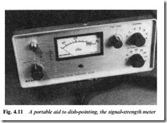
Where the receiver does not incorporate an inbuilt field-strength meter, or where it is physically impractical to use it, a hand-held type can be taken to the dish to aid alignment. The simplest and cheapest type (dish-peaker) gives no absolute indication of signal strength and has a broad frequency response: its indication is the sum total of all
the signals picked up by the dish. It is perfectly adequate for the poining adjustment, however. More expensive meters are tunable to individual transponders and may give a true strength reading in millivolts or dBu. The most comprehensive (and expensive) meters give a spectrum display of the satellite band on a CRT or LCD indicator to show relative and absolute strength of all the carriers received. Either of the latter types can be used for polarisation setting as well as dish-pointing.
Fig. 4.11 shows a simple and inexpensive dish-peaking meter.
Cables and routeing
The link from the dish to the receiver carries frequencies in the range of 950 MHz to 2.15 GHz, too high for use with ordinary UHF TV aerial cables. A special low-loss cable type such as CT100 or H109F must be used: its attenuation at 1.3 GHz is about 23 dB per 100 m, and a maximum run of about 40 m is possible without the use of in-line amplifiers.
In most systems the coax cable itself carries the operating voltage (typically 15 V) to the LNB, and in some cases it carries a d.c. polarisation switching signal as well. Other designs call for a separate pair of conductors for polarity switching. Special cables containing low-loss coax plus separate conductors are available, but it is generally cheaper and more convenient to run a separate (mains-type) twin-core lead alongside the signal cable for this purpose.
The downlead should be provided with a drip loop at each end, and very thoroughly sealed at the points where it enters the LNB and the dwelling: with self-amalgamating tape or a rubber boot at the top, and a mastic sealer at the bottom. Tack up the cable at 50 cm intervals on vertical runs and 20 cm on horizontal runs, following the most unobtrusive route, e.g. under the eaves. Avoid tight bends, which stress the cable physically and cause excessive signal attenuation; a bend radius of 10 times the cable diameter is the minimum acceptable. As a precaution against lightning and static damage it is good practice to ground (earth) the dish metalwork and the braid of the downlead.
Indoor installation
Ensure that the receiver is unplugged (not just switched off) until all wiring and connections are complete. The satellite tuner (some of them run very hot) should be sited on a hard surface with plenty of room for air circulation around it. Most receivers and IRDs (Integrated Receiver/Decoders) come ready tuned, though some require the presetting of polarisation by memorising the setting for each preset channel for each mode, vertical and horizontal. Tuning and station memorisation are described in the user’s handbook – many different systems are in use.
Hook-up
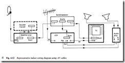
The audio and video outputs are available from the satellite receiver in two forms: baseband, from a SCART socket; and r.f. from a UHF modulator tuned to channel 38 or 39, but adjustable over a range of about 10 channels for older receivers, fully programmable in software for newer types. It is best to use the baseband outputs whenever pos- sible for the better picture and sound quality they offer, their immunity from r.f. interference, and their ability to handle stereo sound signals. Where the TV set or VCR in use does not have SCART sockets, or where they are already fully occupied, the r.f. connection can be used, though careful adjustment of the output channel trimmers of both sat-box and VCR will probably be necessary to avoid mutual interference and the resultant patterning effects.
Even when a baseband connection is present it is still necessary to maintain the r.f. link through the VCR to the TV so that all viewing and recording options are maintained. A typical hook-up is shown in Fig. 4.12. Where the satellite tuner and the VCR are both equipped for stereo sound, their full potential can only be realised with a base- band link: some VCRs and TVs are fitted with two SCART sockets, greatly simplifying hook-up in circumstances like these. SCART pin layout and functions are given in Fig. 24.2.
MAC satellite receivers have RGB outputs as well as those mentioned above, and unless they are connected to the TV set via a SCART lead, wired for RGB, much of the advantage of the MAC TV system is thrown away. VCRs have no means of dealing with RGB signals, but high-band types, e.g. S-VHS format, benefit in terms of picture and sound quality from SCART connections. To help with the sometimes difficult tasks of interconnection and interfacing, various switchboxes are available, some with simple mechanical switches and others with sophisticated auto-switching and routeing based on the ‘status’ flags carried on pins 8 and 16 of the SCART connector system.
The high-quality audio transmissions from satellite services, Hi-Fi VCRs and the Nicam broadcasts described in Chapter 9 have led to a tendency to interconnect audio and video equipment; most video gear is fitted with phono sockets from which leads can be taken to the AUX input of a separate audio amplifier as shown on the right of Fig. 4.12.


