Television fundamentals
For a reasonable understanding of colour television, it is essential that the fundamentals of television are known. As we shall see, all colour systems are firmly based on the original ‘electronic-image dissection’ idea which goes back to EMI in the 1930s, and is merely an extension (albeit an elaborate one) of that system.
Although there are few black and white TVs or systems now left in use, the compatible colour TV system used today by all terrestrial transmitters grew out of the earlier monochrome formats. In the early days, it was essential that existing receivers showed a good black and white picture from the new colour transmissions, and the scanning standards, lumi- nance signal and modulation system are the same. What follows is a brief recap of basic television as a building block of the colour TV system to be described in later chapters.
At the television studio, the scene to be transmitted is projected on a photosensitive plate located inside the TV camera. The scene is repeatedly scanned by a very fast electron beam which ensures that consecutive images differ only very slightly. At the receiving end, a display device such as a plasma or LCD panel or a cathode-ray tube (c.r.t.) is used to recreate the picture by an identical process of scanning a screen by an electron beam. The phenomenon of persistence of vision then gives the impression of a moving picture in the same way as a cine film does. In the UK tele- vision broadcasting system, known as PAL, 25 complete pictures are scanned every second whereas in the US, NTSC is used with 30 pictures per second. Both systems will now be considered.
Scanning
The faceplate of the light-sensitive surface also known as pick-up device is made up of an array of hundreds of thousands of reversed-biased sili- con photodiodes mounted on a chip, typically 7 mm diagonal, arranged in lines and columns. During the active field period, each photodiode acts as a capacitor, and acquires an electrical charge proportional to the amount of light falling on it. The image is sharply focused on the sensor faceplate by an optical lens system. Each diode is addressed in turn by an electron beam which is then addressed individually by the sensor’s drive circuit so that (as viewed from the front) the charges on the top line of photodiodes are read out first, from left to right. Each line is read out in turn, progress- ing downwards, until the end of the bottom line is reached.
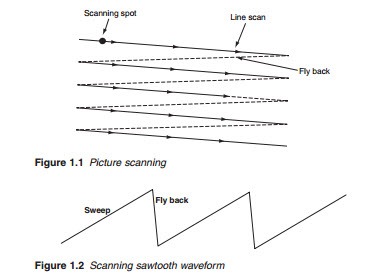
The brightness of each element is thus examined line by line as shown in Figure 1.1 to form what is known as a video signal. A very large number of lines are employed to give adequate representation of the contents of the picture. In the UK’s PAL, 625 lines are used while the USA’s NTSC uses 525 lines. The waveform that provides the scanning movement of the electron beam is the sawtooth waveform shown in Figure 1.2 in which the sweep part provides the line scan and the flyback quickly takes the beam back to the starting position. At the end of each complete picture scan the electron beam moves back to the top of the scene and the sequence is repeated. In the UK, 25 complete pictures are scanned every second, chosen because it matched the 50 Hz frequency of the power supply. It is preferable to match the screen refresh rate to the power source to avoid wave interference that would produce rolling bars on the screen. With each picture containing 625 lines, the line frequency in the UK PAL system is therefore 25 X 625 = 15,625 Hz or 15.625 kHz. In the USA, the NTSC system was originally 30 pictures per second in the black and white system, chosen because it matched the nominal 60 Hz frequency of alternating current power used in the United States. However, with the introduction of colour in the USA, a problem arose as result of a beat frequency between the colour and the sound carriers which could produce a dot pattern on the screen. To avoid this, the original 30 Hz picture rate was adjusted down by the factor of 1000/1001 to 29.97 Hz. With each NTSC picture containing 525 lines, the line frequency is 29.97 X 525 = 15,734 Hz or 15.734 kHz. For high definition (HD), the number of lines is approximately doubled resulting in higher line frequencies as will be discussed in later chapters.
Interlacing
Normal sequential scanning, i.e. scanning complete pictures (625 or 525 lines) at one time followed by another complete picture scan, introduces unacceptable flicker when the picture is reproduced by a c.r.t. This is because once scanned, the brightness of a line fades away gradually as it awaits to be refreshed. Flicker is greatly reduced by a technique known as interlacing. Interlace scanning involves scanning the ‘odd’ lines 1, 3, 5, etc., first followed by the ‘even’ lines 2, 4, 6, etc. Only one-half of the picture, known as a field, is scanned each time. A complete picture therefore con- sists of two fields, odd and even, resulting in a field frequency of 2 X 25 = 50 Hz for the UK system and or 2 X 30 = 60 Hz for the US system.
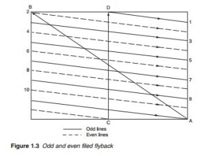
At the end of each field, the electron beam is deflected rapidly back to the beginning of the next scan. The odd flyback ends at the end of the last line of the odd field (point A in Figure 1.3) and the beam is then taken to the start of the first line of the even field (point B) travelling the distance of the screen height. To ensure the same flyback vertical distance and hence same field flyback time for both fields, the even flyback (dotted line) is ended halfway along the last line of the even field (point C) to take the beam to the start of the following odd field (point D) halfway along line 1. This is the reason the total number of lines is chosen to be an odd number.
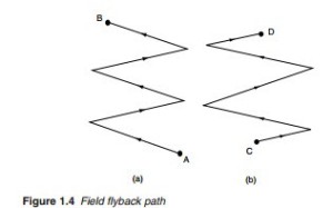
Since the line scan continues to move the electron beam across the screen during the field flyback, the path traced by the beam during the flyback is as shown in Figure 1.4.
In the absence of picture information, scanning produces what is known as a raster.


