DIGITAL RADIO SYSTEMS
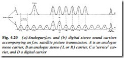
Some analogue satellite transponders convey digital stereo radio channels as well as the analogue f.m. vision and sound carriers. A spectrum diagram for the demodulated signal is shown in Fig. 4.20, where the sound carriers are shown in detail: (a) represents the normal arrangement of analogue sound carriers while (b) illustrates the same region carrying twelve subcarriers phase-modulated with digital sound data. Each carrier contains a digital stereo L-R pair, using quadrature phase shift modulation (QPSK) very similar to that which will be described for Nicam sound in Chapter 9. The main stereo analogue-f.m. carriers at 7.02 and 7.20 MHz are retained for compat- ibility with existing receivers. This configuration provides a maximum of twelve carriers (hence stereo radio channels) alongside a TV channel, or 48 carriers spaced between 0 and 9 MHz if the transponder is given over completely to digital radio.
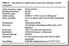
Sampling frequency for the baseband audio signals is 48 kHz at 16-bit resolution, affording a level frequency response from 20 Hz to 20 kHz; dynamic range and signal/noise ratio exceed 90 dB, a specification as good as the audio CD system. Pay channels are scrambled according to the CCITT V.35 specification, and can be reassembled by a decoder and subscription smart card. The parameters for digital satellite radio are given in Table 4.3. An outline of a digital radio set for satellite use is shown in Fig. 4.21. The left- hand side of the diagram is virtually the same as for a conventional satellite receiver, while the right-hand side has something in com- mon with the digital outfits we shall examine in Chapter 12.
The tuner is governed in normal fashion by the microcontroller and the remote control handset, with tuning data stored in an EEP- ROM. The 2nd i.f. signal, bandwidth-limited to 27 MHz by a SAW filter like that shown in Fig. 3.6, is demodulated to baseband within
the tuner module and passed out to an a.g.c.-controlled amplifier. Thus regulated, it goes to an 8-bit converter and phase-demodulator which selects the required carrier signal to produce four output feeds: I (in-phase) and Q (quadrature) carriers; 192 kHz bit-clock pulses; and 24.576 MHz clocking pulse train. They pass into the gate-array IC, custom-designed for this application, where error-correction, decryption and demultiplexing is carried out. Its main products are the data, bit-clock and DAC clock pulses to the Musicam decoder;
4.096 MHz and 12.288 MHz clocks to the smart card reader and veri- fier system; and a digital audio bitstream for decoding outside the receiver. Data, bit-clock and DAC clock pulses pass on to the Musi- cam decoder which decodes the audio datastream for final reassem- bly into L and R analogue signals by the D-A converter. Descrambling depends on an algorithm contined in the user’s smart card, which is read by one chip and verified by a second, using a proprietary program.
Tuning and acquisition of programmes is carried out automati- cally in digital radio sets in a manner similar to the auto-set-up system described for TV and video receivers in Chapter 22. The entire satel- lite band is scanned for DR subcarriers. All their data is stored in an EEPROM memory chip so that the user can call them up at will, aided by an electronic ‘labelling’ system contained in the transmit- ted datastream: it sorts the programmes by category, channel list and ‘favourite’ listing. The search is regularly done to find new programmes and update existing ones.


