Common image format
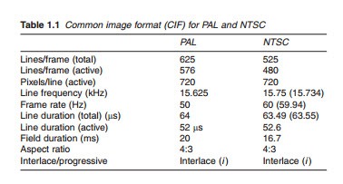
Table 1.1 lists the properties of the 625- (PAL) and 525- (NTSC) line systems known as the common image format (CIF) that has been agreed by European and international standard organisations.
Active lines
While the specified number of lines is 625 and 525 for the respective PAL and NTSC, the actual active lines, i.e. the lines that are actually displayed at the receiving end are fewer. This is because a number of lines are ‘lost’ during the blanking period of the field flyback. These lines are called inac- tive, carrying no visible video information. For PAL, the number of inac- tive lines is 49 resulting in 567 active lines. The corresponding figures for NTSC are 45 and 480.
Aspect ratio
For standard definition (SD) television, the image is normally broadcast with an aspect ratio, i.e. the ratio of width-to-height of 4:3 although the widescreen 16:9 format is also used by several digital television broad- casters. For high definition (HD) television, 16:9 is the specified format.
Pixels and bandwidth
A pixel, short for ‘picture element’, is the smallest active element or dot in an image. A well-defined picture will in general have more pixels than a less-defined one. The resolution of a picture is defined by the number of pixels in the horizontal and vertical directions. The number of pixels in the vertical direction is set by the number of lines. However, the same cannot be said of the number of pixels per horizontal line. This has been interna- tionally set to 720 pixels/line for both PAL and NTSC. This gives a reso- lution for SD television of 720 X 576. For HD television, the figures are higher, namely 1920 X 1080 or 1280 X 720 (PAL) and 720 X 480 (NTSC).
Having determined the number of pixels per line, the total number of pixels in a single picture of a SD television may then be calculated as active pixels/line X active lines. This gives
Video bandwidth
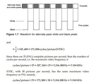
The frequency of the video waveform is determined by the change in the brightness of the electron beam as it scans the screen line by line. Maximum video frequency is obtained when adjacent pixels are alternately black and peak white; this represents the maximum definition of a TV image. For PAL, this means 414,720 alternating black and peak white pixels and for NTSC, 345,600 pixels. When an electron beam scans a line containing alternate black and white pixels, the video waveform is that shown in Figure 1.7, representing the variation of brightness along the line. As can be seen, for any adjacent pair of black and white pixels, one complete cycle is obtained. Hence, for the 10 pixels shown, five complete cycles are pro- duced. It follows that, for a complete picture of alternate black and white pixels, the number of cycles produced is given by 1/2 X number of pixels:
The minimum video frequency is obtained when the electron beam scans pixels of unchanging brightness. This corresponds to unchanging amplitude of the video waveform, a frequency of 0 Hz or d.c. The video band- width is, therefore, 0–5.184 MHz.
Notice here that the specifications outlined by the SD common interface format, results in a common video bandwidth for both systems. That is of course is the purpose of the CIF.


