CENTRAL PROCESSOR
The heart of the syscon is invariably a microprocessor. A 4-bit type is most usual, with on-board ROM containing an instruction set appropriate to the videorecorder design and deck members. Very often this ROM is permanently programmed by or at the request of the equipment manufacturer to suit his design, the rest of the micro being of a standardised type; this ROM programme is defined by the suffix of the type number, very important when the device is replaced in a repair situation. Increasingly, microprocessors are being custom-designed for specific videorecorder or camcorder applications, particularly where the equipment manufacturer is also in the business of designing and producing ICs. This approach greatly simplifies the interfacing circuits between the syscon and its peripheral devices such as keyboards, remote control systems, motors and solenoids. It also permits the use of a single micro for all ‘intelligent’ operations within a budget-priced machine, in which timer, clock, display drive, servo and tape counter operations may be dealt with inside the same package as the syscon process itself, reducing cost, complexity, interconnection links and component count.
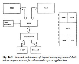
A small RAM capacity is also provided on board the μP chip to store user instructions and deck status data pending decisions or execution. Unlike conventional computing systems where memories, interfaces and codes are separate from the CPU, the one-chip microcomputer used here contains parallel processing CPU, ROM, RAM, I/O ports, programmable timer, control circuit and clock oscil- lator, see Fig. 16.2. Typical ROM and RAM capacities in a syscon microchip are 3000 × 8 bits and 96 × 8 bits respectively. No great speed in operation is required, especially as the micro spends virtu- ally all its time waiting instructions – a clock oscillator rate of 400 kHz is typical, with an instruction cycle of 10 μs.
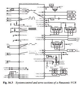
A block diagram of a typical syscon circuit, also incorporating the servo section, is shown in Fig. 16.3. There is little point in attempt- ing to indicate the internal blocks of the microprocessor section; these
devices have to be regarded as ‘black boxes’, and their internal workings are inaccessible anyway. Leaving out the servo section, dealt with in the last chapter, we start at the bottom left-hand corner with chip pins 115/6/7. Normally held high by the adjacent pull-up resistors, these three lines are selectively and sequentially grounded by the wiper contacts of the deck-mounted mode switch to indicate to the syscon the state of the deck mechanics. In this particular design the deck mechanics (see Chapter 18) are driven by a loading motor, here com- manded – via a drive IC – by syscon chip pins 11 and 12.
The other functions which concern us here are operated by the pins in the lower right-hand side of the diagram. IC pin 20 is held low when the safety tab switch S6001 is closed in the presence of a pre- recorded cassette whose tab has been knocked out: this inhibits record mode. IC pin 108 pulses the tape-end sensor LED D6001 which is mounted at the front centre of the cassette shell; when the tape is
fully rewound its light falls on phototransistor Q6002, pulsing down IC pin 94 to inhibit rewind when in stop mode or to invoke stop mode at the end of tape rewinding. Similarly the supply phototransistor Q6003, mounted on the left side of the cassette cradle, sees pulsed IR light from D6001 when the tape is fully wound on to the take-up spool (tape end condition) and signals the fact to IC pin 95 by pulsing it low. Now all forward modes are inhibited and stop or auto-rewind mode entered. When the tape is at an intermediate posi- tion the photosensor transistors are high impedance, the pull-up resistors hold chip pins 94 and 95 high, and any function is permitted.
The reel sensors here are optocoupled types, with the light from the emitter LED in each of IC 6002/6003 being alternately passed to, and blocked from, its phototransistor by castellations on the spool turntable, several times per revolution. The squarewaves thus generated pass into the IC on pins 70 and 71, where they are used not only for deck ‘emergency’ monitoring as described earlier, but to deceler- ate the tape as it approaches rewind-end; and to calculate and display tape time elapsed or remaining. This function is separate from the real-time counter, operated by the CTL pulses at chip pins 82/83.
As the pin-count of this IC suggests (it’s a 124-lead flatpack) it has many functions in addition to those shown here. We shall meet some more of them in Chapter 22.

