Adaptive de-blocking filter
One of the main deficiencies of the MPEG-2 coding process is ‘blocking artefacts’. These are caused by the division of the image into blocks for the purposes of transform coding. The artefacts occur at the boundaries of
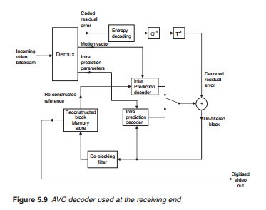
these blocks and are most visually prominent with high degree of quanti- sation at periods of extreme compression stress. To overcome this, AVC incorporates a de-blocking filter as part of the decoding process as illus- trated in Figure 5.9. The incoming bitstream contains video information on a block by block basis. Each block is defined by three coded components: residual error, motion vector and intra-prediction mode parameters. The purpose of the demultiplxer is to separate these three components. The coded residual error is decoded in three stages in reverse order of the cod- ing process at the transmitter stage: entropy decoding, inverse quantisation (Q-1) and inverse transformation (T-1). For the reference intra-predicted blocks, the intra-parameters are fed into the intra-decoder to obtain an intra-predicted block which is added to the residual error to produce the original block. These blocks are fed back into the intra-prediction decoder to be used as a basis for decoding subsequent blocks. They are also fed into the de-blocking filter to smooth the boundaries and reconstruct the blocks into a digitised I frame. The reconstructed I frame is stored in mem- ory to be used as a basis for decoding the P frames. For decoding the P frames, the decoded residual error is now added to the inter-predicted blocks that were obtained using the motion compensation vector. These blocks are de-blocked and used to reconstruct a digitised video which is used for display purposes. It is also fed into a memory store for decoding subsequent P frames.
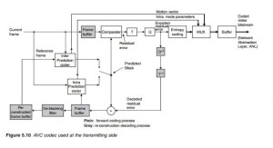
De-block filtering is an adaptive process which must function in the same way in all decoders and that includes the decoding part of the AVC codec at the transmitting end where it is known as an in-loop de-blocking as illustrated in Figure 5.10. For the I frame, the intra-prediction coder produces predicted video, block by block and sends out the intra-mode parameters (block size and mode) to the multiplexer for inclusion in the video bitstream. The predicted blocks from the intra-coder are compared with the current blocks and a residual error is produced which is then transformed and quantised and following entropy coding is fed to the mul- tiplexer. Following inverse quantisation (Q-1) and inverse transformation (T-1), the residual error is added to the intra-predicted blocks from the intra-coder to produce the original block. These are fed back to the intra- coder for the purposes of encoding the remaining I-frame blocks. They are also fed into the de-blocking filter to smooth the edges and re-construct the complete I frame in the same way as it is produced by the decoder at the receiving end. For the P frames, the inter-prediction coder uses the ref- erence I frame in the re-constructed de-blocked frame buffer to produce motion vectors and inter-predicted blocks. The motion vector parame- ters are fed directly to the multiplexer while the inter-predicted blocks are compared with the actual block of the current frame and a residual error is produced which is transformed, quantised and entropy coded before going into the multiplexer. In the same way as the intra-predicted frame, the P frame is reconstructed for use in subsequent inter-coding.
The de-blocking filter has two benefits: block edges are smoothed, im- proving the appearance of the image and reduced residual error as a result of the use of filtered macroblocks for motion compensation prediction.
Filtering is applied to vertical or horizontal edges of 4 X 4 blocks affect- ing up to three pixels on either side of the boundary. The choice whether to filter or not and the strength of the filtering depends on the type of blocks under consideration and the gradient across them. Filtering is stronger at places where there is likely to be significant blocking distortion such as the boundary of intra-coded macroblocks. To assess the gradient, the de-blocking filter examines a set of vertical and horizontal pixels across the block boundary and assesses changes in their values. A step change could indicate a blocking artefact or may be a genuine transition in the image. The threshold is dynamically set taking into account the degree of quantisation. A low level of quantisation indicates a very small gradient across the boundary which most likely is due to image features and should be left alone. On the other hand, when the degree of quantisation is high, blocking distortions are likely and the filter is turned on. Thus, if the step change is smaller than the specified threshold, it is assumed to be genuine and the filter is switched off. Otherwise, the filter is brought in and the filtering strength is set according to the boundary type and the calculated gradient.
De-blocking filters have to be modified when an interlaced video is used because the vertical separation of the pixels in a field is twice that of a frame.


