Fault finding on plasma television
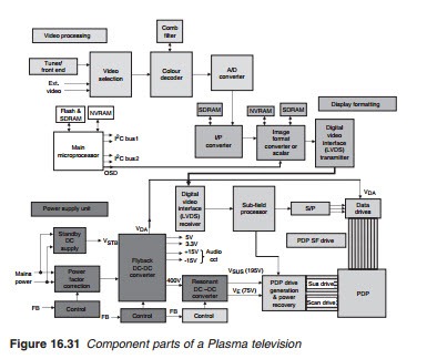
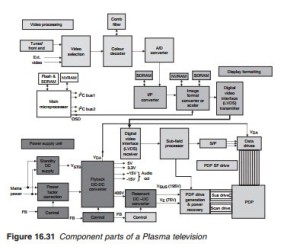
Before looking into faults and fault-finding techniques, let us examine the sequence of events following a cold switch of a plasma television receiver. Figure 16.31 shows the component parts of a Plasma TV receiver capable of receiving analogue terrestrial broadcasts. The audio section is not shown as it is relatively independent once stereophonic audio is extracted
following demodulation at the tuner/front end. Most modern plasma receivers include a DVB decoder circuit which can then receive and decode digital terrestrial TV broadcasts, known as free view in the UK. Integrated digital television (iDTV) will be considered later in Chapter 18.
When the TV receiver is switched on, d.c. power builds up in three dis- tinct stages: PFC followed by the Flyback d.c.–d.c. converter followed by the resonant converter. First the PFC control oscillator generates the necessary PWM waveform to regulate the PFC section and produce a d.c. output that is fed into the flyback converter. Once this d.c. voltage is up, the flyback converter begins the switching operation to build up the 400 V d.c. output. This d.c. voltage is then used as the d.c. input for the resonant converter which generates the d.c. voltages required to generate the sustain and scan waveforms. Switched d.c. is obtained from the secondary of the flyback transformer to generate the necessary processing and audio d.c. power.
The build-up of the d.c. power is followed by the microprocessor start- up routine. First the microprocessor will download the start-up program from the Flash memory chip into SDRAM to commence the start-up rou- tine. If Flash is faulty or the program is corrupted, the process will be halted and the set will go into standby. The microprocessor will also exam- ine its NVRAM for individual and other specified settings to incorporate them into the start-up routine. Once again, if NVRAM is faulty or its con- tents are corrupted, start-up will be halted and the set will go into standby. The start-up routine involves testing and initialising all programmable and processing chips to be ready to receive and process the video and audio information. This process is invariably carried out by I2C serial con- trol bus. More than one I2C is used. As a result of increased integration, some of the chips shown as discrete units may be incorporated into a sin- gle chip as was indicated earlier. For instance flash and NVRAM may be imbedded within processing chips. In this case, upgrading or re-program- ming Flash is no longer a simple matter of changing the memory chip itself with an already programmed Flash. Upgrading must now be carried out by running software on a PC and downloading it on the imbedded Flash via a serial port. Other advanced integration includes incorporating the scan, the I/P and the format converters into a single image scalar chip.
Faults on a plasma receiver may be divided into several categories. Data, scan and sustain drive faults are as follows (refer also to Chapter 10):
● Single black horizontal line suggesting a fault in a scan drive.
● Single black vertical line suggests a fault in a data drive.
● Black vertical band points to failure of a group of data lines corresponding to where the band is on the screen.
● Black horizontal band points to grouped scan drives failure. Check the scan pulse waveforms at the output of the drives corresponding to the position of the band, line by line to confirm.
● Sustain or common drive failures will generally result in a blank screen as all sustain electrodes are connected together, hence the name common.
However, in some cases, the sustain electrodes are divided into separate groups, a sustain failure may result in a horizontal black band. Check both scan and sustain waveforms.
● Vertical black, white or colour lines 1 or 2 cm apart. The cause is a failure in the shift register embedded within one of the data tape connector which forms part of the PDP. The panel has to be replaced.
In all of the above, the fault could be in the display panel itself, in which case, the panel must be replaced.

