ENCODING AND TRANSMISSION
Most of the cost of providing a Nicam stereo service is in the studio and control room, where high-performance equipment must be provided, and close attention paid to acoustics, noise level, balancing and mixing. The actual Nicam encoding equipment consists of a handful of ICs, and the relatively low-level carrier is not difficult to accommodate at transmitters, especially those using modern designs of r.f. amplifier.
A−D conversion
The two sound channels of the Nicam system are completely independent and have total immunity from crosstalk. They can therefore be used for two monaural (i.e. dual-language) transmissions or for data signals, and provision is made for these in the specification. The most common application is the conveyance of L and R stereo sound signals, however, and it is this that we shall examine.
The baseband L and R signals coming from the studio are first pre-emphasised according to the CCITT J17 recommendation, which boosts the level of higher-frequency components for noise-reduction purposes.
Each is then sampled at 31.25 μs intervals, corresponding to 32 kHz rate, and offering a maximum response of 16 kHz. Input frequen- cies are in fact limited to 15 kHz in sharp cut-off filters at the A−D converter inputs to prevent aliasing and consequent distortion. Each sample is now quantised to 14 bits, which gives 16 238 possible sound signal levels. L and R sampling is carried out simultaneously in separate A−D converters, after which L-channel signals are called A samples and R-channel signals are called B samples.
Digital compression
It is not possible, within the constraints of an already tightly packed TV channel allocation, to transmit the full 14-bit data, so the rate is reduced to 10-bit for its passage over the air. The reduction is carried out in such a way, however, that most of the advantage of 14-bit resolution is retained. This is done by moving the sampling baseline, in effect, according to the status of the audio signal being sampled; during quiet and delicate passages, equal-to-14-bit resolution is achieved. At sharp transitions in signal level, and for very loud sounds, the resolution falls to 10-bit standard, but in the circumstances this is not discernible by the listener. Normally a 10-bit system offers a signal-to-noise ratio of about 60 dB. With the dynamic compression system used here, the subjective effect of an 80 dB S/N radio is achieved.
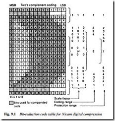
The principle of digital compression used for Nicam is shown in Fig. 9.1. Running across the diagram are all possible combinations which could make up a 14-bit word. For transmission all the bits in
the shaded blocks are retained. The most significant bit (MSB) at left passes through regardless. The 13th bit is discarded if it is the same as the 14th; the 12th bit is discarded if it is the same as nos 13 and 14, and the same is done with nos 11 and 10. If at the end of this process any word has more than 10 bits, sufficient bits are trimmed from the least significant bit (LSB) end to reduce it to 10 bits, as shown at the right top and bottom of the diagram.
So long as the decoder is continuously fed with information on which of the five possible coding ranges is in use at the compressor from moment to moment, it can reconstitute a very close approximation to the original signal. This scale factor is conveyed by a 3-bit data signal as shown in Fig. 9.1. The various scale factors require different levels of protection against data corruption in transmission, as shown in the right-hand column of the diagram.
Data protection
Because of the risk of data corruption or distortion in the transmis- sion path, protection must be provided in the form of a check or parity bit added to the end of each word. Here even parity is used to check on the word’s 6 most significant bits. At the encoder the 6 MSB are added together, modulo-two, to give a result of 1 or 0. The par- ity bit is given the same value so that the modulo-two addition of the 6 MSB and the parity bit should always be 0. At the decoder, parity checking detects simple errors and permits correction.
The parity bits are also used to signal scale factor information to the decoder. They are modified in accordance with a look-up table held in memory at both ends of the chain. The 3-bit scale factor word is extracted at the decoder by majority-decision logic, while retain- ing (except during circumstances of heavy data corruption) the parity-check facility. The scale factor information enables the decoder to recreate any bit in the left half of the block of Fig. 9.1 which was removed during the digital compression process. Any bits removed from the LSB side of the word (right-hand top and bottom in the diagram) cannot be restored, but their loss is masked by the fact that their samples are not crucial ones noise-wise.
Thus full 14-bit resolution is given to the small vulnerable signals corresponding to range 5, falling in four steps to 10-bit resolution in range 1, which corresponds to the largest audio signals. This economy in bit-rate has little or no subjective effect on the listener.
For scale factor signalling purposes the protected 11-bit words are grouped together in blocks of 32, each block lasting for 1 ms. A 3-bit code word is sent with each block to indicate scale factor as shown in Fig. 9.1. Since only one such word has to cover 32 consecutive data words there is some inaccuracy here: not all words receive optimum expansion. In practice the decoder gets reliable information on the magnitude of the largest signal in each block, at a rate sufficient to track the fastest perceptible changes in loudness, and this achieves a subjectively high S/N ratio.
Bit interleaving
In a data transmission system protection must be given against impulsive interference or dropout, which otherwise would make an irreparable ‘hole’ in the datastream. It is achieved by interleaving the bits at the coder and reassembling them in the correct order at the decoder. This spreads and fragments any errors and enables the simple parity-check system to cope with quite large short-term errors.
The data is written into memory at the sending end, then read out non-sequentially according to a ROM address-sequencer which has a complementary counterpart in the decoder. By this means bits which were initially adjacent are transmitted at least 15 bits apart. Any damage is now distributed among several words, each repair- able by parity protection and/or error concealment by interpolation.
Control data
So far we have only examined the signal data, that which conveys the audio information. To control and synchronise the decoding and signal-routeing processes at the receiver extra data must be added.
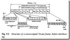
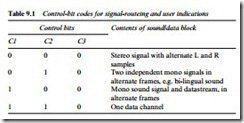
Fig. 9.2 shows the make-up of a broadcast data-frame, which occupies 1 ms and contains 728 bits. The frames are sent continuously, with no gaps between them. First comes a frame alignment word (FAW) to initiate and synchronise the decoding sequence. It consists of 8 bits and always has the sequence 01001110. Following this is the application control word consisting of 5 bits, C0 to C4. C0 is the frame flag bit, which alternates between 0 and 1 at eight-frame intervals. It defines a 16-frame sequence, and is used to synchronise changes in the type of data being sent. Bits C1, C2 and C3 indicate the nature of the data broadcast according to Table 9.1 – it operates indication lights and route-switches at the receiver. C3 remains unchanged for all these options, but provides spare capacity which may be used in future for other sound and data coding options. C4 is a reserve sound switching flag, set to 1 when the Nicam system carries the same sound programme as the conventional f.m. sound carrier, and to 0 otherwise. It is used to mute the audio amplifier/ loudspeaker when data other than TV sound is being sent, and for
switching between f.m. and Nicam sound systems as circumstances and users require.
Following the application control bits come 11 AD (additional data) bits whose use and contents have yet to be defined. The rest of the frame is given over to the sound data whose conditioning we have already examined.
Audio data
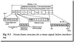
The sound data bits are arranged in 64 11-bit words as shown in Fig.
9.2. For a stereo programme the A samples (L channel) and B samples (R channel) are sent alternately: 32 of each. In a monaural transmission the frame is arranged with two 32-word blocks (n and n + 1) placed end-to-end in a single frame, as shown in Fig. 9.3. The sound signal is carried in odd-numbered frames, leaving gaps which can be used if required for a second monaural (e.g. bi-lingual) sound track or for the transmission of other forms of data: for downloading into a computer, for instance. For mono sound, Table 9.1 indicates that the control code would be 100 (switches receiver to mono mode); for two independent mono signals the code changes to 010, and M1 or M2 can be selected by the user.
Scrambling
The data will be used to modulate a carrier, and fixed patterns in the datastream set up fixed sideband patterns around the carrier. This is undesirable from the point of view of interference to co-channels and adjacent channels in the broadcast band, so the datastream must be scrambled to make it appear random and noise-like. The frame alignment words are not scrambled because they initiate the descram- bling process at the decoder.
At each end of the chain is a PRSG (pseudo-random sequence generator) which generates a sequence of binary digits in a fixed and repeatable pattern. Each PRSG is reset on the last bit of the frame alignment word, and its output is added modulo-two to the data bits. The effect is of a completely random bitstream in the transmission channel.
Modulation
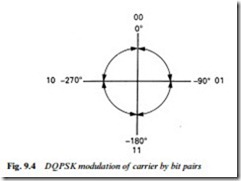
The data is now ready for transmission and must be modulated onto an r.f. carrier. The system used is four-phase modulation, which is economical of bandwidth. The carrier has four possible rest states – 0°, 90°, 180° and 270° – and is switched between them by the Nicam data. A serial to 2-bit parallel converter changes the serial data into a series of 2-bit pairs, which can only be 00, 01, 10 or 11. Each of these alters the carrier phase by a different amount, as shown in Fig. 9.4, from its previous rest state. Only a 00 bit pair will have no effect on carrier phase.
Carrier phase changes, then, take place at 2-bit intervals with a maximum shift of half a cycle of carrier frequency. To avoid sudden sharp changes of carrier phase the data is fed through a spectrum shaping filter on its way to the DQPSK modulator. This has the effect of ‘smoothing’ the transitions and quietening the sidebands. For system I transmissions (UK, Ireland etc.) the filter used gives a maximum sideband spread of 700 kHz. For system B/G transmis- sions as used in most of Western Europe a sharper filter is used to limit the spread to 500 kHz and thus avoid interference with the nearby f.m. sound carrier.
Nicam carrier
In system I the f.m. sound carrier is 6 MHz above the vision carrier at a relative level of –10 dB. The Nicam carrier is spaced 6.552 MHz (nine times bit rate) above vision carrier at a level of –20 dB, see Fig. 9.5(a). For system B/G transmitters the Nicam carrier is at +5.85 MHz as shown in Fig. 9.5(b).
The Nicam format is compatible with the MAC/packet system used for satellite transmissions so that chip sets developed for the one can be used for the other.
