COLOUR RECORDING
What has been described so far is only concerned with the luminance and audio components of the TV signal. The space between zero and 1 MHz in the tape-frequency spectrum (Fig. 13.1) is reserved for the chroma signal, and to prevent it being encroached upon by the lower sideband of the luminance f.m. signal, the risetime and frequency range of the latter are reduced in the pre-modulator luminance processing stages; any shortcomings in this bandpass filter will permit luminance and chroma signals to cross-modulate, with consequent patterning in the played-back picture.
The colour signal is recorded direct onto the tape without any form of modulation system. It is already encoded and based on a 4.43 MHz subcarrier whose phase and amplitude relative to the accompanying burst signal describe the colours in the picture. To interfere in any way with the chroma signal would be to invite hue and saturation errors; to decode and demodulate it to baseband for recording and encode/modulate it during replay would be a complex
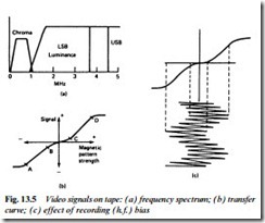
and unpredictable business. The PAL (or other) colour signal can- not be recorded in its 4.43 MHz form as broadcast, however: it is above the frequency range of the baseband signals that the system can handle; the timing jitter introduced by the mechanics of the recording/playback process would play havoc with the phasing of the subcarrier signal and hence the hue; and the bandwidth demand would be too great to accommodate in the limited tape spectrum. Two processes are carried out on the chroma signal to slot it into the 0–1 MHz space assigned to it. It is bandwidth-restricted in a band- pass filter which limits its sideband excursions to ±500 kHz on each side of the carrier frequency; and it is frequency-shifted by a heterodyne process to a new base frequency around 600 kHz. Thus is formed a lower-definition, lower-frequency chrominance signal with all characteristics of phase, amplitude and burst features intact. This new frequency allocation and ‘clipping of wings’ tailors it for the position it occupies in the tape-frequency spectrum: it is added to the f.m. luminance signal and passed to the heads for recording. Fig. 13.5(a) shows the complete signal spectrum on tape.
FM carrier as recording bias
Because the transfer characteristic of magnetic tape is not linear, Fig. 13.5(b), a recording bias must be provided and added to the signal
to be recorded if severe distortion is not to take place. It is normal practice in audio tape recorders to add a relatively high frequency (say 40 kHz) switching signal to the audio waveform before it is applied to the recording head; the locally generated bias signal is very carefully controlled in amplitude so that its peaks sit in the centres of the linear sections A−B and C−D in Fig. 13.5(b). As the record signal is rapidly switched between these two centre-points by the bias signal, it is printed in linear fashion as magnetic patterns in the tape, as Fig. 13.5(c) shows. The ability to work on both sections of the tape transfer curve increases the replay level and improves S/N ratio. In the colour-under recording system used in domestic videorecorders the f.m. luminance carrier acts as a.c. bias source for the low- frequency chrominance signal. The two are added in the recording amplifier, and the variations in ‘bias’ frequency matter not at all – during replay a low-pass filter in the chrominance amplifier removes all signal components above 1 MHz.
For the scheme to work the levels of both f.m. luminance carrier and chrominance signal must be closely controlled, and their preset amplitudes depend very much on the characteristics of the tape to be used. The level of the f.m. carrier (luminance writing current) must be set to take the tape’s magnetic coating halfway to saturation in each direction; the chrominance record level then must be trimmed so that the largest expected colour-signal amplitude (fully saturated cyan or red) drives the magnetic surface of the tape to just short of saturation in the positive direction, and just short of non-linearity in the negative direction. Correct settings of these levels ensure low signal distortion and maximum S/N ratio. In the audio world, differ- ent tape materials (oxide, metal, chrome etc.) are available, and need different bias and drive settings for optimum performance; for video- recorders the levels are preset to the type of tape available for that format. The metal and metal-evaporated tapes used with Video 8 format have very different bias, coercitivity and saturation characteristics to conventional tape as used in other formats. Where colour is not present in the signal to be recorded (mainly vintage films) a useful gain in noise performance can be achieved by increasing the gain of the luminance recording amplifier; a 6 dB boost in writing current drives the tape into magnetic saturation in both directions on each cycle of f.m. carrier.

