FREQUENCY MULTIPLEX
An alternative approach to the provision of high-quality sound with video is the frequency-multiplex system, used in the V8 format. V8, as part of its specification, makes use of metal-powder and metal- evaporated (MP and ME) tapes, whose magnetic coating thick- nesses are only 3 and 0.15 micron respectively, and therefore unsuitable for depth-multiplex techniques. The V8 sound system caters for a monaural sound track conveyed by a single f.m. carrier at 1.5 MHz with maximum deviation of ±100 kHz, see Fig. 14.3(b). Separate audio heads are not used here: the 1.5 MHz f.m. sound carrier is added to the luminance f.m. and colour-under signals for pas- sage via the recording amplifier to the video recording heads.
To avoid mutual interference the audio carrier writing current is held to 12 dB below nominal chroma writing current, which itself is some 6 dB below luminance writing current. Further, the relatively high video f.m. carrier frequency (4.2–5.4 MHz) ensures that little luminance sideband energy is present in the 300 kHz-wide spectrum- slot reserved for the f.m. audio carrier and its sidebands. In V8 the colour-under frequency is based on 732 kHz with sideband spreads of about 500 kHz, so that the upper chroma energy limit on the tape- frequency spectrum is about 1.25 MHz, again avoiding interference from the sound carrier.
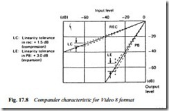
The electronic processing circuit for V8 f.m. audio is just the same as that described above, using 2:1 logarithmic compression and expansion (Fig. 17.8) carried out by the same form of r.m.s. detector and VCA. A similar VCO and PLL f.m. modem system is also used. For camcorder application an audio-recording high-pass filter is used to cut off frequencies below 200 Hz in order to suppress wind, lens- motor and handling noises. An upper frequency limit of 15 kHz is also set in the baseband signal chain to permit correct operation of the noise-reduction circuit. During replay the off-tape f.m. audio signal is picked out by a sharp cut-off bandpass filter centred on 1.5 MHz, then applied to a 2-field dropout compensation circuit. For this simpler 1-channel system a single miniature 48-pin chip caters for all audio-f.m. and noise-reduction processes during both record and playback, for which internal electronic switches are provided; such external components as are required are limited to RC and LC networks for filtering and response shaping.
Stereo in Video 8 formats
Although the original specification for V8 provided only for mono sound, a stereo variant was arranged by having a second carrier for L-R audio information at 1.7 MHz, with the ‘mono’ channel now carrying L+R information. The two channels are separated during replay in a simple add/subtract matrix.
