Air blowers
The description air blower is applied to types of air pump designed to deliver small volumes of air at low to moderate pressure. Some types can also work in reverse as exhausters, the Roots pump being a typical example. Other types have fan type impellers capable of moving larger volumes of air at low pressures and are called fan blowers or turbo-blowers. They differ from positive displacement pumps which are designed to work at higher pressure ratios.
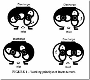
The Roots blower, Figures 1 and 2, employs two identical rotors turning in opposite directions inside a cylindrical casing. The rotors intermesh but maintain positive clearance by timing gears. Internal lubrication is unnecessary, so the air is delivered free of oil. Compression takes place by back-flow every time a rotor tip uncovers the discharge port. High volumes of air can be displaced since the rotors can be driven at high speeds by synchronous or directly-coupled electric motors. The pressure generated is usually less than 1 bar in a single stage (see the chapter on Compressor Performance).
Discharge Discharge
Each revolution of the rotors causes four volumes of air to be conveyed through the blower. The cross-sectional area of the rotor is, to a close approximation, equal to one-half of the cross-section of the rotor diameter, so the total theoretical delivery is given by:
As explained in the chapter on Compressor Performance, the overall efficiency is not as good as if there were a built-in volume compression ratio. This inefficiency is tolerated for the sake of simplicity of production. Because the pressure rise is small the actual difference in power is usually not significant.
In addition to the power needed to compress the air, there is a further power loss to overcome friction in the timing gears, bearings and seals as well as dynamic losses in the compression chamber; the total is of the order of 5%. An advantage of this type of blower is that, because there is no internal compression, the off-load power is approximately equal to this small amount.
Positive-displacement blowers
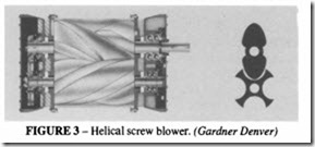
The boundary line between a compressor and a blower is not always clear. One machine which can be considered as either a blower or a compressor is the helical screw machine illustrated in Figure 3.
This lies between the helical screw compressor and the Roots blower. It is more efficient than the Roots (up to 10%, at maximum pressure), but is more expensive to manufacture because of the complexity of the screw manufacture. It requires timing gears to maintain correct meshing. This machine can generate a pressure of 1.2 bar or a vacuum of 50 %.
Fan blowers
A fan impeller consists of a number of blades mounted at a pitch angle and assembled on, or integral with, a hub mounted on a driven shaft. Rotation generates a slip-stream in a similar manner to an airscrew, although the efficiency is low compared with a true airscrew for several reasons: usually the geometric pitch along the length of the blade is not constant; a large number of blades are provided, which increases the volumetric flow at the expense of efficiency; the cross-section of the blades is not of aerofoil form, indeed they are often made from flat steel plate, curved to an approximate aerodynamic form. Fans are used to move large volumes of air at very low pressures and are to be found in ventilation systems, engine and compressor cooling, conveying, vacuum cleaning and supercharging.
Fan concepts and definitions
The effect of a fan is to change both the static pressure and the air velocity from those measured upstream of the fan (the inlet) to those measured downstream (the outlet). There will also be changes in temperature and density but these are small and are frequently ignored in the analysis. If VI and v2 are the inlet and outlet air velocities and PI and P2 the inlet and outlet static pressures, the following definitions apply:
If both the fan inlet and outlet are open, the fan total pressure is equal to the fan velocity pressure, and the fan static pressure is zero. As the volume flow decreases, the fan total pressure increases, reaching a maximum value at a volume flow which depends on the particular fan design. Such characteristics may be seen in Figure 4. When interpreting manufacturer’s catalogues, this factor should be borne in mind.
Fan performance characteristics
The subject of fan design is outside the scope of this chapter, but it may be helpful to examine some of the design parameters which can be used to evaluate fan performance. Dimensional analysis leads to the following pairs of relationships (each pair is a representation of the same relationship expressed in a different form). The first expression of each pair is to be preferred because the coefficient is independent of the units used (provided of course that the units are consistent), but both are to be found in technical literature, so are included here. When using the second form, care must be taken to use the proper units.


