ENERGY BALANCE FOR UNSTEADY-FLOW PROCESSES
During a steady-flow process, no changes occur within the control volume; thus, one does not need to be concerned about what is going on within the boundaries. Not having to worry about any changes within the control volume with time greatly simplifies the analysis.
Many processes of interest, however, involve changes within the control volume with time. Such processes are called unsteady-flow, or transient-flow, processes. The steady-flow relations developed earlier are obviously not applicable to these processes. When an unsteady-flow process is analyzed, it is important to keep track of the mass and energy contents of the control volume as well as the energy interactions across the boundary.
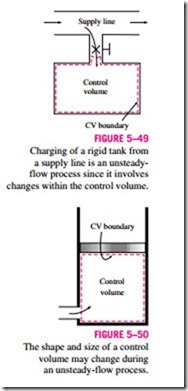
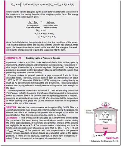
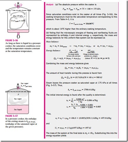
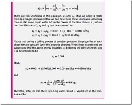
Some familiar unsteady-flow processes are the charging of rigid vessels from supply lines (Fig. 5–49), discharging a fluid from a pressurized vessel, driving a gas turbine with pressurized air stored in a large container, inflating tires or balloons, and even cooking with an ordinary pressure cooker.
Unlike steady-flow processes, unsteady-flow processes start and end over some finite time period instead of continuing indefinitely. Therefore in this with the rate of changes (changes per unit time). An unsteady-flow system, in some respects, is similar to a closed system, except that the mass within the system boundaries does not remain constant during a process.
Another difference between steady- and unsteady-flow systems is that steady-flow systems are fixed in space, size, and shape. Unsteady-flow systems, however, are not (Fig. 5–50). They are usually stationary; that is, they are fixed in space, but they may involve moving boundaries and thus boundary work.
Mass Balance
Unlike the case of steady-flow processes, the amount of mass within the control volume does change with time during an unsteady-flow process. The magnitude of change depends on the amounts of mass that enter and leave the control volume during the process. The mass balance for a system undergoing any process can be expressed as
where i = inlet, e = exit, 1 = initial state, and 2 = final state of the control volume; and the summation signs are used to emphasize that all the inlets and exits are to be considered. Often one or more terms in the equation above are zero. For example, mi = 0 if no mass enters the control volume during the process, me = 0 if no mass leaves the control volume during the process, and m1 = 0 if the control volume is initially evacuated.
Energy Balance
The energy content of a control volume changes with time during an unsteady-flow process. The magnitude of change depends on the amount of energy transfer across the system boundaries as heat and work as well as on the amount of energy transported into and out of the control volume by mass during the process. When analyzing an unsteady-flow process, we must keep track of the energy content of the control volume as well as the energies of the incoming and outgoing flow streams.
The general energy balance was given earlier as
The general unsteady-flow process, in general, is difficult to analyze because the properties of the mass at the inlets and exits may change during a process. Most unsteady-flow processes, however, can be represented reasonably well by the uniform-flow process, which involves the following idealization: The fluid flow at any inlet or exit is uniform and steady, and thus the fluid proper- ties do not change with time or position over the cross section of an inlet or exit. If they do, they are averaged and treated as constants for the entire process.
Note that unlike the steady-flow systems, the state of an unsteady-flow sys- tem may change with time, and that the state of the mass leaving the control volume at any instant is the same as the state of the mass in the control volume at that instant. The initial and final properties of the control volume can be determined from the knowledge of the initial and final states, which are completely specified by two independent intensive properties for simple compressible systems.
Then the energy balance for a uniform-flow system can be expressed explicitly as
where e= h + ke + pe is the energy of a flowing fluid at any inlet or exit per unit mass, and e = u + ke + pe is the energy of the nonflowing fluid within the control volume per unit mass. When the kinetic and potential energy changes associated with the control volume and fluid streams are negligible, as is usually the case, the energy balance above simplifies to
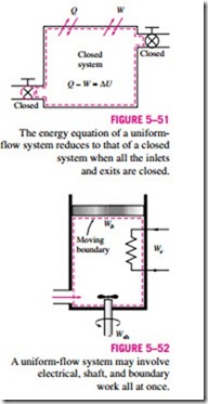
Note that if no mass enters or leaves the control volume during a process (mi = me = 0, and m1 = m2 = m), this equation reduces to the energy balance relation for closed systems (Fig. 5–51). Also note that an unsteady-flow system may involve boundary work as well as electrical and shaft work (Fig. 5–52).
Although both the steady-flow and uniform-flow processes are somewhat idealized, many actual processes can be approximated reasonably well by one of these with satisfactory results. The degree of satisfaction depends on the de- sired accuracy and the degree of validity of the assumptions made.
