MOBILE COMPRESSORS
The expression “mobile compressor” refers to a compressor mounted on a chassis and supplied complete with an engine and all the necessary control systems, requiring only fuel or some other kind of primary power to generate compressed air. It can be mounted on wheels or skids. Usually it will also have a canopy to protect the working machinery from the weather and to reduce noise transmission. Figure 1shows three examples of a two wheel rotary compressor capable of supplying air for a construction site. The pressure is up to 13 bar and the delivery up to 280 1/s.
The expression “portable compressor”, although strictly a misnomer, is also commonly used; a compressor that can be easily lifted and moved from place to place is called “transportable”. Such compressors can be carried on the back of a truck or mounted inside a van.
Mobile compressors are frequently encountered by the roadside or on construction sites, where they are used to supply air for roadbreaking tools or drills and a wide range of contractor’s tools. When used on the road, the chassis and wheels have to meet the appropriate legislation for road-going trailers. When used only on construction sites or in quarries, a simpler and cheaper chassis can be used. For smaller sizes (less than about 80 1/s capacity), a two-wheel chassis is standard; for intermediate sizes up to about 300 1/s both two- and four-wheel types are available. For large sizes and for rugged sites such as in quarries four wheel types are standard. A four-wheel chassis can either have turntable or automotive type steering on the front wheels. Independent torsion-bar suspension may be fitted for road use. A lifting eye or bale protruding through the canopy roof is fitted as standard.
Construction-use compressors usually have a storage facility to hold one or more road breakers and lengths of hose. Depending on the application, a towable compressor may incorporate the following features:
• A straight tow bar with levelling leg (U.K. use)
• A cranked adjustable towbar with jockey wheel (European models)
• Towing lights and indicators
• Towing eye or ball coupling
• Cable operated parking brakes
• Overrun and pneumatic brakes
• Security features such as a lockable control panel door and the lifting bale accessible only from within the canopy
• Integrallubricator
• Electric generator
Most canopies are made of steel, with gull-wing or side and front doors to give access to the controls for starting and for servicing. Ifsilencing is incorporated, the canopy is lined with sound deadening material. Smaller road-going compressors may have canopies made of glass fibre reinforced plastic. Portable compressors are also available skid-mounted as an alternative to a wheeled undercarriage.
Mobile compressor types are frequently used in the dirty environment of a construction site or quarry, far removed from the comparatively clean atmosphere of a factory, so special attention has to be paid to intake filtration for both compressor and engine. Cooling arrangements depend on the type of engine used. Air-cooled engines rely on fan cooling, water-cooled engines have a conventional automotive type radiator. The oil cooler (in an oil-flooded compressor) will probably be a conventional shell-and-tube cooler.
There will usually be found safety features such as automatic shut-down when the air delivery temperature, the engine coolant temperature or engine oil pressure exceeds a safe maximum. Indicators will give a visual warning when filters need changing.
A fuel tank with a capacity equivalent to one shift continuous operation is standard. Most of the canopies of portable units are lockable for security reasons.
The exigencies of the equipment hire market, into which many mobile compressors are sold, leads to their use in very adverse conditions, often with only rudimentary servicing.
The price is highly competitive, so the extra cost of sophisticated control systems would be neither necessary nor desirable.
Pressure and capacity of portable compressors
The standard supply pressure of portable compressors is 7 bar, because practically all construction and hand-held tools are designed to operate at this pressure as a maximum. Most tools will work adequately (but with a reduced performance) at a pressure varying between 4 bar and 7 bar. This flexibility makes compressed air a very versatile medium for use by contractors.
Higher pressures, up to about 20 bar, are also available, intended for such specialist purposes as the supply of air for high performance quarrying drills.
The capacity of portable compressors varies from 1.5 m’ /min up to about 40m3/min. Note that the traditional designation for the capacity of portable compressors is ft3 /min, and even the products of European suppliers frequently have a reference designation which can be traced to the capacity in these units. (Note that I m’ /min= 16.71/s = 35.3 ft3 /min).
One frequently comes across the expression one-tool, two-tool up to five-tool compressor. The tool referred to is a concrete breaker or paving breaker with an air requirement of 1.5 m 3 /min (25 1/s). Such compressors are capable of running that number of tools simultaneously.
Mobile compressor noise legislation
The mobile compressor is frequently blamed as one of the noisiest items of construction plant which affect the environment. In fact the public are probably unable to differentiate between noise from the compressor and noise from the tool connected to it. The tool is by far the largest producer of noise, and in a typical roadside site, noise from the tool swamps that from the compressor. Despite this, there has been much pressure on the legislators to introduce regulations to limit the permissible noise level of compressors. This has culminated, in the EC, in regulations forbidding the supply of compressors emitting more than a prescribed noise.
Similar regulations also prohibit the supply of noisy tools (see the Section dealing with contractor’s tools), but the levels set for tools are much higher than for compressors.
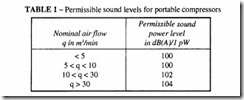
The test method is described in EC Council Directive 84/533/EEC. It consists in placing the compressor on a concrete base in the centre of a hemispherical array of microphones,
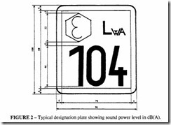
then integrating the total sound power over the area of the hemisphere. There is a limited number of Government Approved test stations capable of carrying out a type test in accordance with the Directive. Arrangements differ in the various countries of the Community but a compressor approved in one can be freely imported and sold in any of the others. Figure 2 shows the designation plate that is attached to an approved compressor. The value 104 shown on that plate represents the sound power in dB(A) as measured by the testing station.lt may be less than that required in the Directive; it may not, of course, be greater.
These regulations have no force outside the Community although other Western countries have similar, if not stricter, rules.
There may be some confusion about the designation of the sound emitted by a compressor (or any equipment for that matter). The approved method now is to specify the sound in terms of sound power against a base of I pW (10.12 W). This takes into account that a piece of machinery emits a different amount of noise in different directions, and therefore the only true assessment of its noisiness is to measure the total noise emitted over a surface enclosing it. However large the surface is, the total noise is the same. This is the principle behind the Directive. An alternative way of specifying the sound emitted by a compressor, which is frequently quoted in manufacturers’ literature, is by the use of the Pneurop/CAGI Test Code. This is a simple method of noise measurement consisting of taking an average of four readings of sound pressure level at a distance of 7 m from the side of the compressor (not from its centre as in the EC Code). An approximate method of converting from sound power to sound pressure at 7 musing the Pneurop/CAGI Code is to subtract from the former 26 dB for a small compressor (up to 10m3 /min) and 27 dB for larger ones.
Out of the widespread use of the Pncurop/CAGI Code there arose the description of a compressor as standard, silenced or super-silenced. Standard means that no particular sound proofing has been applied, silenced means that the level of silencing is down to 75 dB(A) at 7 m, super-silenced means that a level of 70 dB(A) has been achieved.
If one wishes to determine how much noise an operator or a member of the public is exposed to, the local level of sound pressure has to be calculated from the sound power value and the distance from the centre of the compressor. The required relationship, ignoring such factors as the presence of reflecting objects and the directivity of the noise source, is:
Methods of reducing the noise level of portable compressors
Most of the noise is generated by the engine, and since the engines used are standard industrial units with no particular attention paid to silencing for the compressor market, the burden is on the compressor manufacturer to apply sound reduction techniques to the canopy enclosure. The following techniques have been found useful:
• Line the canopy with sound-deadening material. The use of such materials as absorbent foam in the engine/compressor section where there could be contamination by fuel and oil leading to a fire hazard should be avoided. Double skinning could be used instead.
• Use flexible engine mounts between engine and chassis.
• Ensure the enclosure is complete. Use undertrays. Any opening doors should be well sealed. Instruments must be capable of being read from outside without opening the doors.
• The canopy should be soundly made, reinforced where necessary to prevent panel drumming and rattle.
• Extra engine exhaust silencing.
• Line the cooling air intake and exhaust passages with sound deadening material.
This is an important point to observe- much noise can escape through the cooling air passages. Use silenced exhaust valves.
• Compressor intake from inside canopy.
• Mount canopy flexibly on chassis.
Some or all of these methods are capable of reducing noise level down to the required level. See chapter on Compressor Noise Suppression for further techniques.
In countries with high ambient temperatures, the incorporation of sound insulation material may have an adverse effect on the cooling of the compressor. Some of the insulation can be omitted but only for those countries where it is permitted.
Van mounted mobile compressors
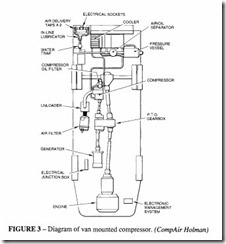
Utility companies sometimes require the versatility of a compressor which, in addition to supplying compressed air to operate roadside equipment such as a road breaker, can also act as an electric generator for lighting purposes or as a supplier of hydraulic power. Such a unit can be mounted in a van, taking as its power source the van engine via a power take off from the main drive shaft. The compressor and generator can be under the floor of the van leaving the body free for use as a mobile workshop. There are a number of these available. Figure 3 shows diagrammatically how the various items are connected. A vehicle such as the one shown in the figure can supply 2.8 m3/min of air at 7 bar pressure and 6 kVA at a choice of voltages.


